
Fuel Supply Device for a Motor Vehicle

Inactive Publication Date: 2008-12-11
SIEMENS AG
View PDF16 Cites 18 Cited by
  • Summary
  • Abstract
  • Description
  • Claims
  • Application Information

AI Technical Summary

Benefits of technology

[0016]In order to further facilitate fitting of the components of the inventive fuel supply device in the fuel tank vent lines of the venting device are secured to the wall of the fuel tank.
[0017]In order to further reduce the costs of manufacturing the fuel suppl

Problems solved by technology

A disadvantage of the known fuel supply device is that the suction jet pump is very costly to fit in the venting device and requires a secondary flow of fuel deliv

Method used


Image

  • Fuel Supply Device for a Motor Vehicle
  • Fuel Supply Device for a Motor Vehicle

Examples


Example

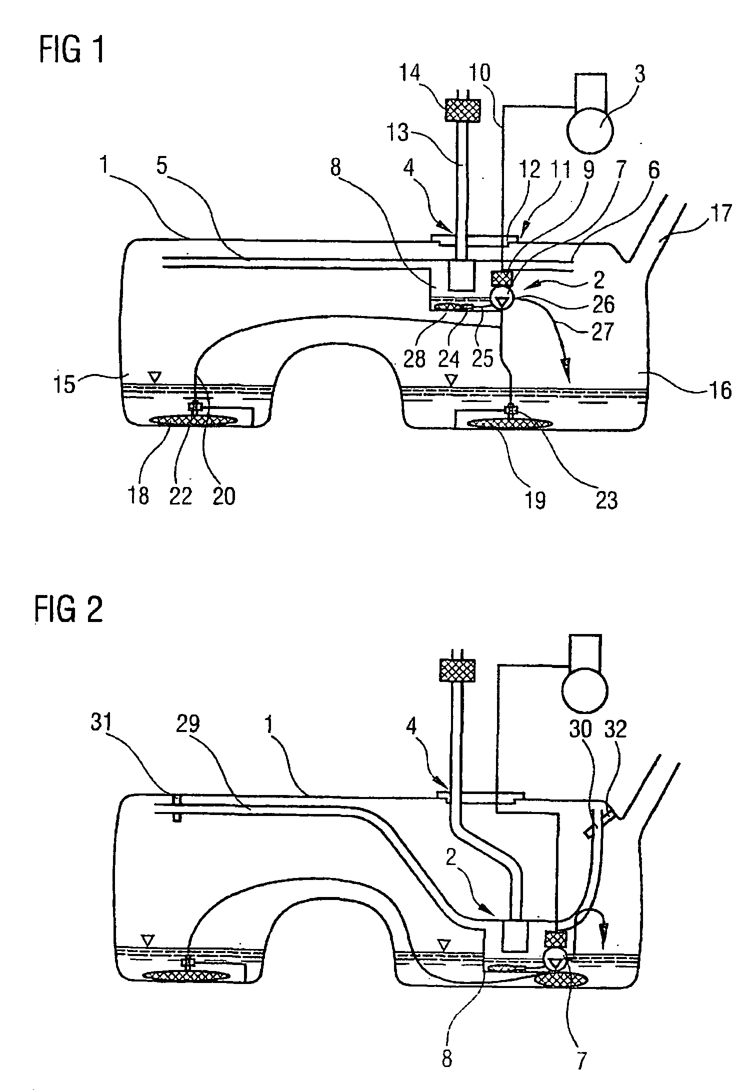
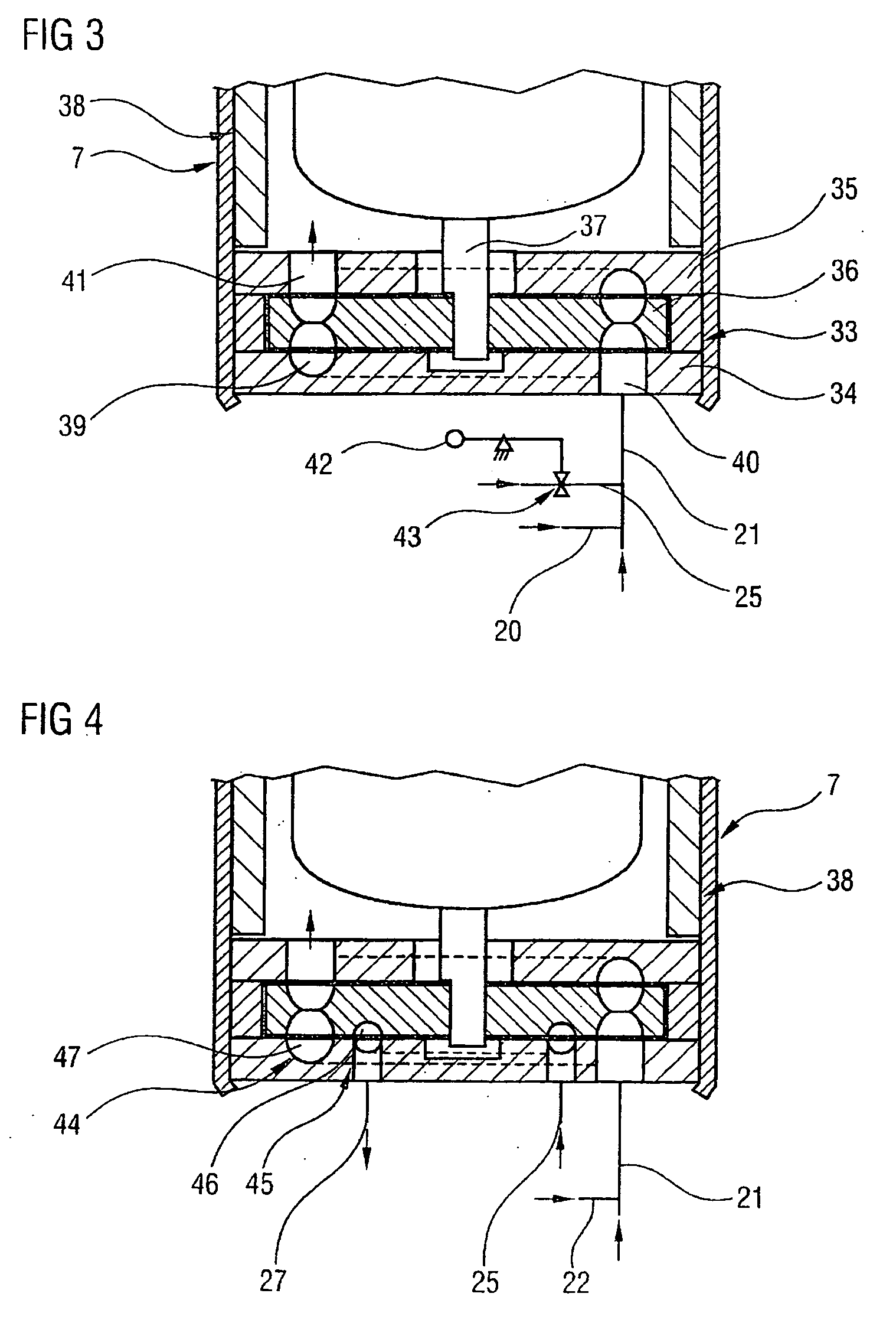
[0031]FIG. 3 shows a section through a first embodiment of the fuel pump 7 of the fuel supply device 2 in FIG. 1 or 2. The fuel pump 7 has a pump stage 33 in the form of a side-channel pump with an impeller 36 driven between two housing parts 34, 35. The impeller 36 is fixed on a shaft 37 of an electric motor 38. A delivery chamber 39 of the pump stage 33 is led from an inlet duct 40 arranged in one of the housing parts 34 through the impeller 36 to an outlet duct 41 arranged in the other housing part 35. Fuel delivered by the fuel pump 7 flows through the electric motor 38 and is delivered into the feed line 10 represented in FIGS. 1 and 2. Lines 20, 21 leading into the chambers 15, 16 and the line 25 leading to the intake connection 24 in the bubble removal vessel 8 are connected to the inlet duct 40. The line 25 led to the intake connection 24 in the bubble removal vessel 8 moreover has a valve 43, which is operated by a float 42 and which closes the line 25 when the fuel filling...


PUM


Abstract

The invention relates to a fuel supply device (2) for a motor vehicle, which comprises a fuel tank (1). An intake connection (24) of a fuel pump (7) is located in a ventilation device (4). The fuel pump (7) simultaneously takes in fuel from the fuel tank (1) and from the ventilation device (4). For this purpose, the fuel pump (7) and a bubble removal container (8) of the ventilation device (4) are configured as a single structural unit.

Description

BACKGROUND OF THE INVENTION[0001]The invention relates to a fuel supply device for a motor vehicle, comprising a fuel tank, a fuel pump drawing in fuel from the fuel tank and designed to deliver the fuel to an internal combustion engine of the motor vehicle, a venting device for balancing the fuel tank pressure with the ambient pressure when filling up or in operation, and a device for drawing off fuel from the venting device into the fuel tank.[0002]Such fuel supply devices are commonly used in modern motor vehicles and are known in practice. In the known fuel supply device the fuel pump is fixed to the bottom of the fuel tank separately from the venting device and delivers fuel into a feed line leading to the internal combustion engine of the motor vehicle. From the feed line a line branches off to a suction jet pump arranged in the venting device. The suction jet pump delivers fuel from the venting device into the fuel tank. The components of the venting device are likewise fitte...

Claims


Application Information

Patent Timeline
IPC IPC(8): F02M37/20B60K15/035F02M37/10
CPCB60K15/03504B60K2015/03467B60K2015/03509F02M37/106F02M37/20Y10T137/2496B60K15/035
Inventor KROGULL, CHRISTIANMEYER, KNUTREITER, FRANKFUEHLING, STEFANKOHLHAAS, HELMUT
Owner SIEMENS AG
Learn More