Scanning module

Inactive Publication Date: 2008-12-11
FOXLINK IMAGE TECH
View PDF3 Cites 26 Cited by
  • Summary
  • Abstract
  • Description
  • Claims
  • Application Information

AI Technical Summary

Problems solved by technology

However, the components of the conventional CIS scanning module are so many and it is inconvenient to assemble, moreover, the tolerances are accrued and then the precision is affected, the coop

Method used


Image

  • Scanning module
  • Scanning module
  • Scanning module

Examples


first embodiment

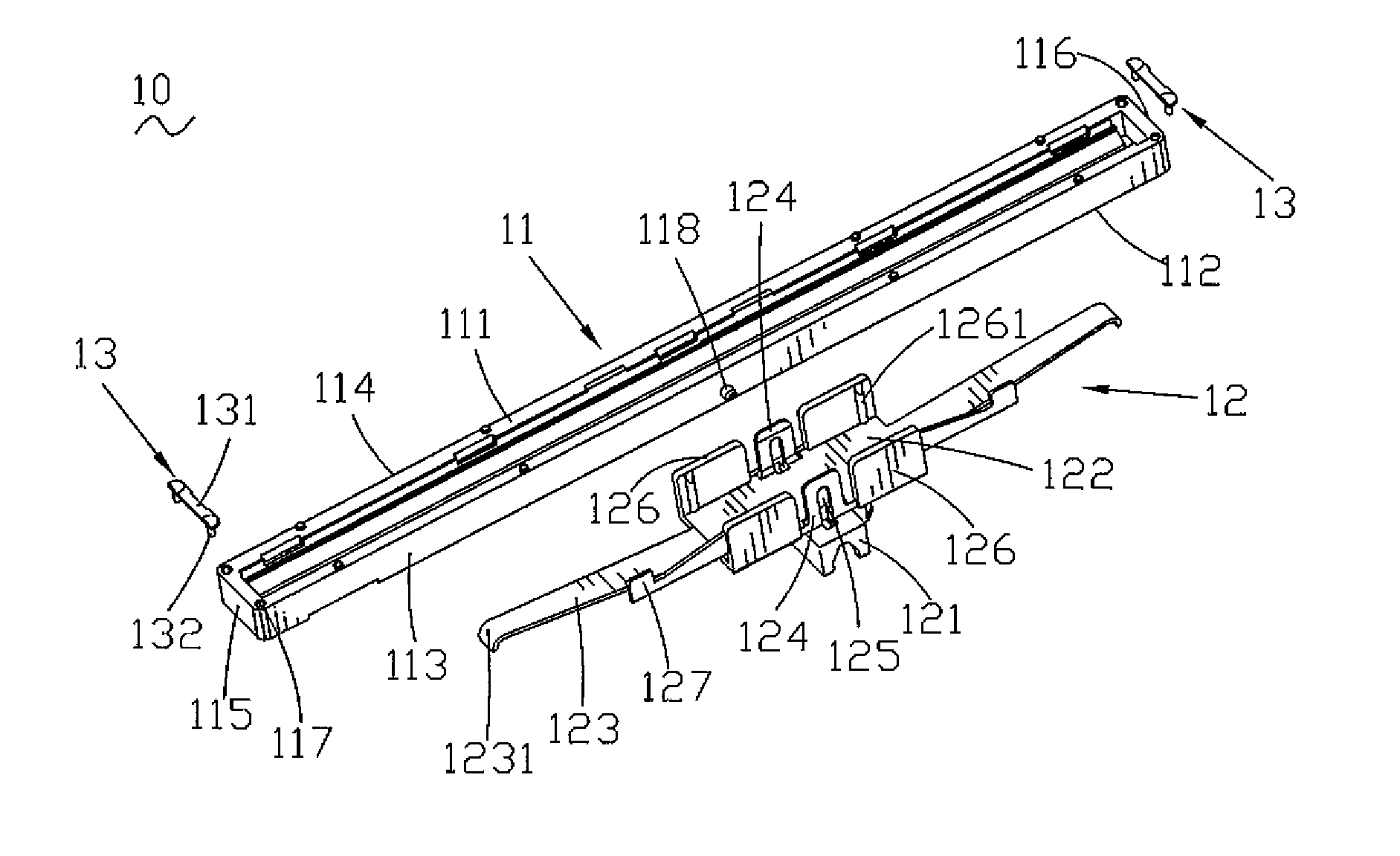
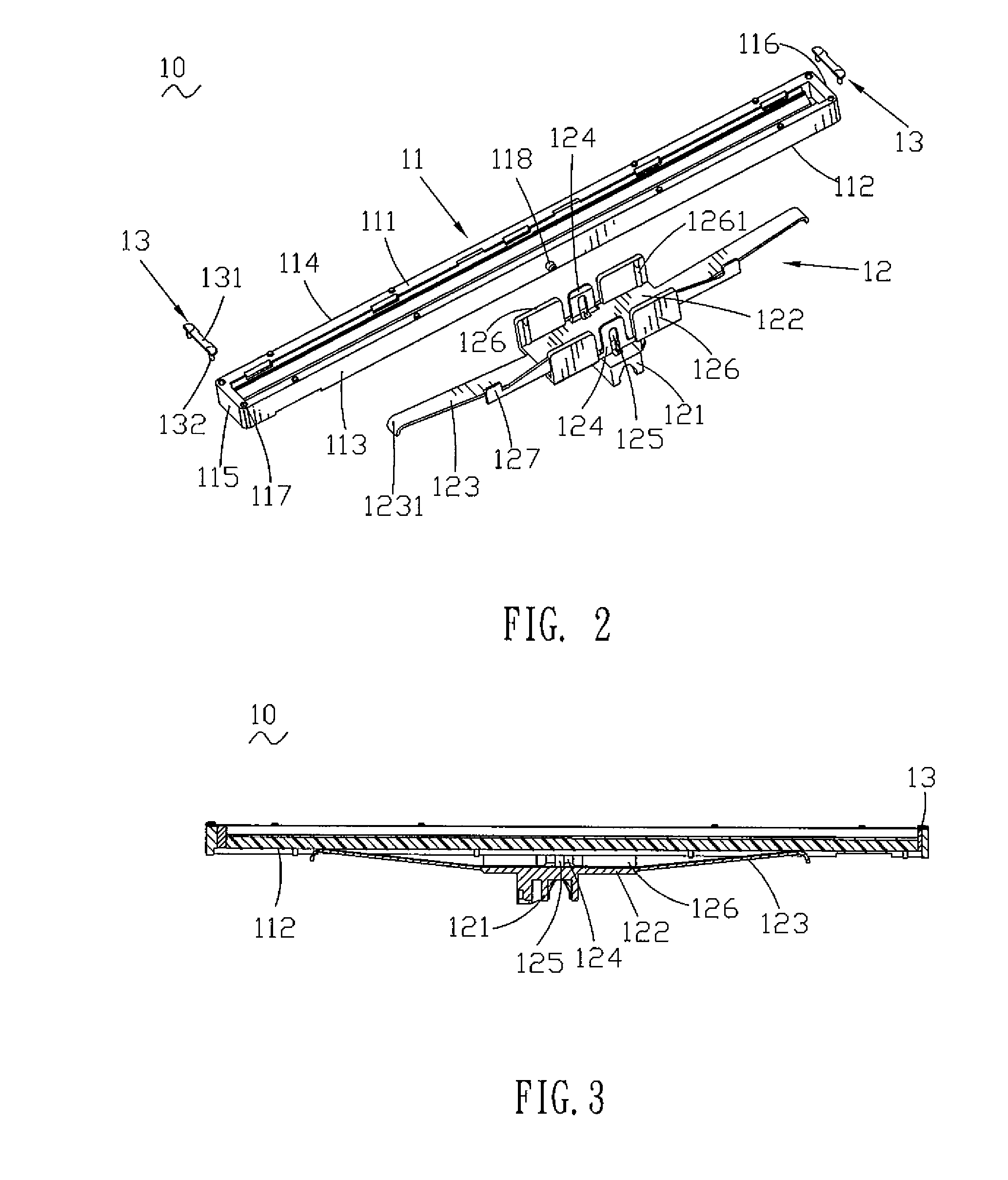
[0017]Please refer to FIGS. 1-2, the present invention is shown. A scanning module 10 includes a sensor unit 11, a supporting base 12 and a pair of long-wearing piece 13.

[0018]The sensor unit 41 is about cuboid-shaped, having a top surface 111, a bottom surface 112, a front surface 113, a back surface 114, a left surface 115 and a right surface 116. The top surface 111 contacts with a document-supporting board of a scanner (not shown). The sensor unit 11 defines a locking hole 117 at each corner of the top surface 111, a positioning pillar 118 projects from the middle portions of the front surface 113 and the back surface 114 respectively.

[0019]The supporting base 12 has a guiding portion 121, a rectangular positioning board 122 is mounted on the guiding portion 121, the middle portions of the two sides of the positioning board 122 extend sideward and bends upward to form an elastic arm 123 respectively, the end of the elastic arm 123 further bends downwards to form a contact portio...

second embodiment

[0023]FIGS. 4-5 show a scanning module 20 of a second embodiment according to the present invention. The scanning module 20 includes a contact image sensor unit 21 and a supporting base 22.

[0024]The structure of the contact image sensor unit 21 of the present embodiment is similar to the contact image sensor unit 11 of the first embodiment, having a top surface 211, a bottom surface 212, a front surface 213, a back surface 214, a left surface 215 and a right surface 216. A positioning pillar 218 projects from the middle portions of the front surface 213 and the back surface 214 respectively.

[0025]The structure of the supporting base 22 of the present embodiment is similar to the supporting base 12 of the first embodiment, having a guiding portion 221, a rectangular positioning board 222 is mounted on the guiding portion 221, the middle portions of the two sides of the positioning board 222 extend sideward and bend upward to form a elastic arm 223 respectively, the elastic arm 223 ha...

third embodiment

[0027]FIGS. 6-7 show the present invention. The third embodiment includes a contact image sensor unit 31 and a supporting base 32.

[0028]The structure of the contact image sensor unit 31 of the present embodiment is similar to the contact image sensor unit 11 of the first embodiment, having a top surface 311, a bottom surface 312, a front surface 313, a back surface 314, a left surface 315 and a right surface 316. A positioning pillar 318 projects from the middle portions of the front surface 313 and the back surface 314 respectively.

[0029]The structure of the supporting base 32 of the present embodiment is similar to the supporting base 12 of the first embodiment, having a guiding portion 321, a rectangular positioning board 322 is mounted on the guiding portion 321, the middle portions of the two sides of the positioning board 322 extend sideward and bend upward to form a elastic arm 323 respectively. The elastic arm 323 has a contact portion 3231 at the end. The middle portions of...


PUM


Abstract

A scanning module includes a contact image sensor unit and a supporting base. The contact image sensor unit has a top surface, a bottom surface, a front surface and a back surface. The supporting base has a guiding portion, a positioning board mounted on the guiding portion, the two sides of the positioning board extends sideward and bends upward to form an elastic arm respectively, the contact image sensor unit is placed on the positioning board and the elastic arm elastically contacts the bottom surface of the contact image sensor unit. The two sides of the supporting base of the scanning module have an elastic arm respectively, the elastic arm contacts the contact image sensor unit directly and makes sure that the contact image sensor unit contacts the glass tightly.

Description

BACKGROUND OF THE INVENTION[0001]1. Field of the Invention[0002]The present invention relates to a scanning module, and more particularly to a CIS (Contact Image Sensor) scanning module.[0003]2. The Related Art[0004]Scanner is an input device of the computer, which scans the picture, the photo, the film and the document and inputs the scanning image into the computer. Recent scanner includes CCD (Charge-Coupled Device) scanner and CIS (Contact Image Sensor) scanner. The CCD scanner focuses the light on an optic lens module, the light signal is converted into electrical signal and forms the image. The CIS scanner doesn't need the optic lens module, as a result, the power is saved and the volume is smaller than that of the CCD scanner, so the CIS scanner is portable in requirement. In recent years, the technology of the CIS scanner is developing.[0005]Please refer to FIG. 1, a conventional CIS scanning module includes a sensor unit 41 for reading the image, a frame 42 for supporting t...

Claims


Application Information

Patent Timeline
IPC IPC(8): H04N1/04
CPCH04N1/0313H04N1/1017H04N1/103H04N1/193H04N2201/0081H04N2201/02404
Inventor WU, KUO-KUANGLEE, YUEH-SHINGCHU, TE-YOU
Owner FOXLINK IMAGE TECH
Why Eureka
Try Eureka