Ultrasonic image processing apparatus and method for processing ultrasonic image

a processing apparatus and ultrasonic image technology, applied in the field of ultrasonic image processing apparatus and ultrasonic image processing, can solve the problems of inability to analyze the wall motion of the myocardium, inability to track the endocardium, and difficulty in real-time analysis of the motion of the region of interes

Active Publication Date: 2008-12-11
TOSHIBA MEDICAL SYST CORP
View PDF11 Cites 40 Cited by
  • Summary
  • Abstract
  • Description
  • Claims
  • Application Information

AI Technical Summary

Benefits of technology

The technical effect of this patent is to create an ultrasonic imaging device and process that can show movement within certain tissues in real-time.

Problems solved by technology

The technical problem addressed in this patent text relates to the difficulty of analyzing and displaying the motion of a specific region of interest in live body tissues like the heart's myocardium in real-time using existing methods that rely on image data or patterns. Existing techniques require operators to manually define the boundaries of the target area and can only provide limited information about its overall motion. There is also no clear guidance on how to effectively display the motion information of a region of interest using the available tools.

Method used


Image

  • Ultrasonic image processing apparatus and method for processing ultrasonic image
  • Ultrasonic image processing apparatus and method for processing ultrasonic image
  • Ultrasonic image processing apparatus and method for processing ultrasonic image

Examples


first embodiment

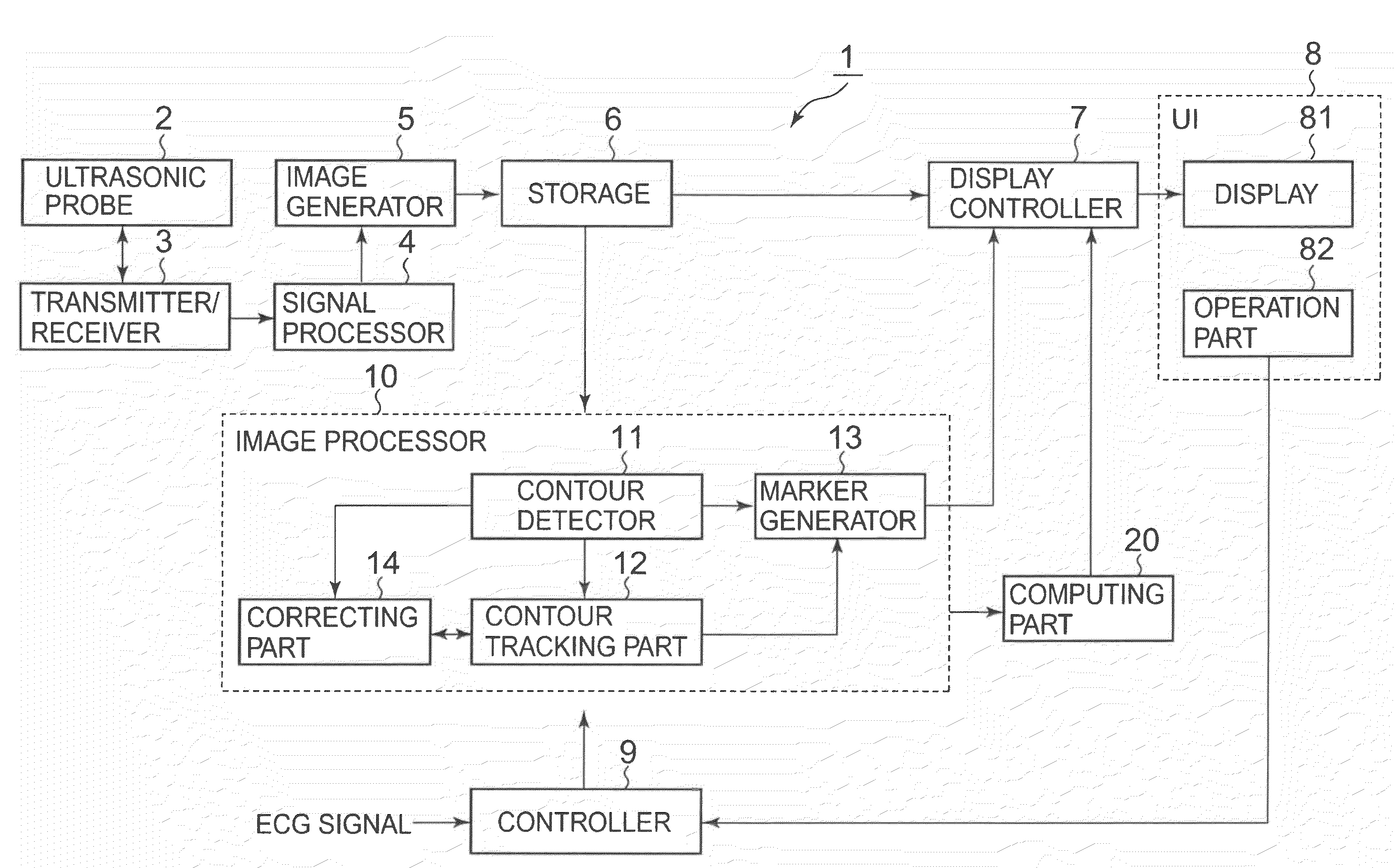
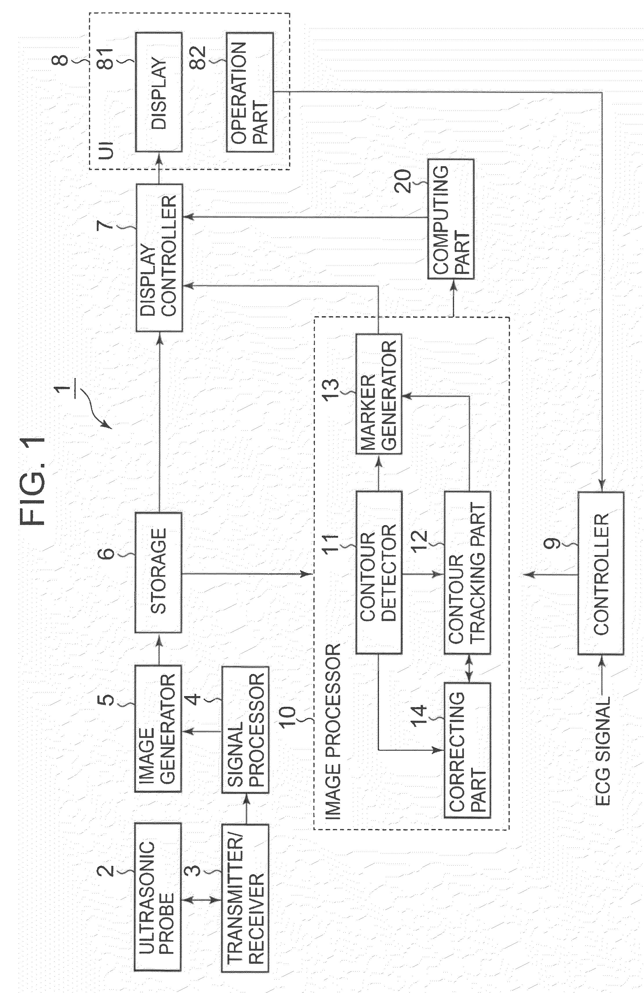
[0025]An ultrasonic imaging apparatus according to a first embodiment of the present invention will be described with reference to FIG. 1. FIG. 1 is a block diagram showing the ultrasonic imaging apparatus according to the first embodiment of the present invention.

[0026]An ultrasonic imaging apparatus 1 comprises: an ultrasonic probe 2; a transmitter / receiver 3; a signal processor 4; an image generator 5; a storage 6; a display controller 7; a user interface (UI) 8; a controller 9; an image processor 10; and a computing part 20. Further, the storage 6, the display controller 7, the user interface (UI) 8, the image processor 10 and the computing part 20 configure an ultrasonic image processing apparatus.

[0027]As the ultrasonic probe 2, a 1-dimensional array probe (1D array probe) in which a plurality of ultrasonic transducers are arranged in a row in a predetermined direction (a scanning direction), or a 2-dimensional array probe (2D array probe) in which a plurality of ultrasonic tr...

second embodiment

[0101]Next, the ultrasonic imaging apparatus according to a second embodiment of the present invention will be described referring to FIGS. 5, 6A and 6B. FIG. 5 is a block diagram showing the ultrasonic imaging apparatus according to the second embodiment of the present invention. FIGS. 6A and 6B are views showing images acquired by the ultrasonic imaging apparatus according to the second embodiment of the present invention.

[0102]In the aforementioned first embodiment, wall motion information is obtained by tracking the contour of the endocardium and the contour of the epicardium on a 2-dimensional plane based on tomographic image data of a 2-dimensional image. In the second embodiment, wall motion information is obtained by tracking a 3-dimensional contour of the endocardium and a 3-dimensional contour of the epicardium based on volume data of a 3-dimensional image.

[0103]An ultrasonic imaging apparatus 1A according to the second embodiment comprises an image processor 10A instead o...


PUM


Abstract

A contour detector detects the contour of a specific tissue based on ultrasonic image data having been acquired in a predetermined time phase. A contour tracking part obtains the position of each of points composing the contour of a specific tissue in ultrasonic image data having been acquired in each time phase, by pattern matching for each time phase. A computing part obtains motion information indicating the motion state of a specific tissue in each time phase, based on the position of each of points composing the contour in each time phase. A display controller controls a display to display an ultrasonic image based on ultrasonic image data having been acquired in each time phase, for each time phase. Furthermore, the display controller controls the display to display the motion information in each time phase, on each occasion of each time phase.

Description


Claims


Application Information

Patent Timeline
Owner TOSHIBA MEDICAL SYST CORP
Why Eureka
Try Eureka