

Mobile telephone jamming system for automobiles
- Summary
- Abstract
- Description
- Claims
- Application Information
AI Technical Summary
Benefits of technology
Problems solved by technology
Method used
Image

Examples
Embodiment Construction
[0037]The drawings will now be discussed in reference to the numerals provided therein so as to enable one skilled in the art to practice the present invention. The drawings and descriptions are exemplary of various aspects of the invention and are not intended to narrow the scope of the appended claims. It will also be appreciated that various aspects of the invention may be discussed or shown separately but may be coupled with other aspects of the invention in a single embodiment. Thus, the individual figures should not be viewed as distinct inventions, but rather as showing portions of the invention as a whole. Furthermore, it will be appreciated that various embodiments will achieve various aspects of the invention and these aspects should not be viewed as limiting the appended claims.
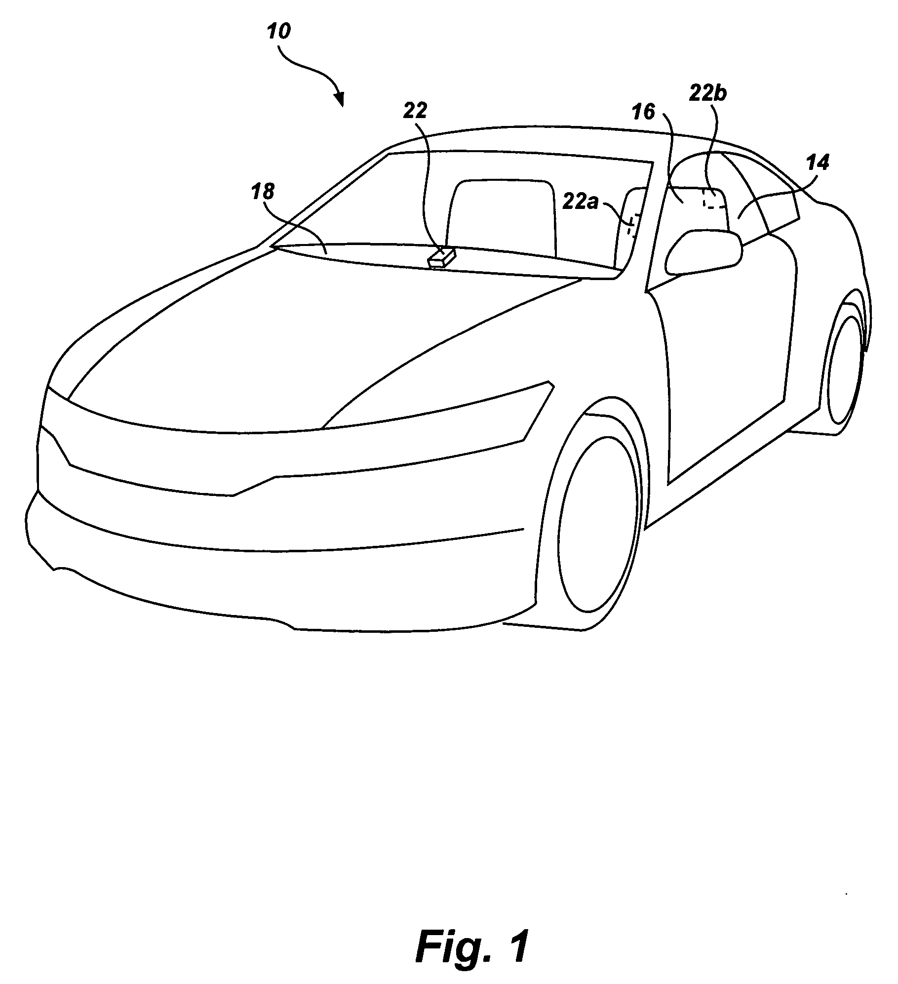
[0038]Referring now to FIG. 1 there is shown an automobile, generally indicated at 10. The automobile 10 includes a cabin 14 in which an individual sits in a seat 16. It will be appreciated in acco...
PUM
 Abstract
Description
Claims
Application Information