Safety cone placing device and method

a safety cone and placing device technology, applied in the field of road safety, can solve the problems of inability to place cones in a particular place in an automatic fashion from a moving vehicle, inability to deliver cones, and inability to meet the needs of users, so as to reduce the time it takes to deliver and place safety cones, and improve safety. the effect of reducing the tim

Inactive Publication Date: 2007-08-09
WORLDWIDE SAFETY
View PDF39 Cites 8 Cited by
  • Summary
  • Abstract
  • Description
  • Claims
  • Application Information

AI Technical Summary

Benefits of technology

[0021] The advantage of the present invention is that it provides automatic placement of a plurality of safety cones from a moving vehicle. This is enabled by the use of safety cones with a flexible means that easily resists perturbations and could optionally be held in spring-loaded position in the receptacle to assist in the release from the receptacle. There would be no more need for a person to manually deliver and place the safety cones. Human interaction would only be required to control the release of one or more safety cones. The present invention therefore provides for increased safety. Furthermore, the time it takes to deliver and place the safety cones is significantly decreased compared to manual placement. It would also allow the driver of the vehicle delivering the safety cones to no longer worry about the cone placement and could therefore pay more attention to the accident or event that initiated the safety cone placement.
[0022] The objectives and advantages of the present invention will be understood by reading the following detailed description in conjunction with the drawings, in which:
[0023]FIG. 1 shows an exemplary embodiment of a device removably attached to a vehicle according to the present invention;
[0024]FIG. 2 shows an exemplary embodiment of a device removably positioned in a trunk of a vehicle according to the present invention;
[0025]FIG. 3 shows exemplary embodiments of a receptacle according to the present invention;
[0026]FIGS. 4-6 show exemplary embodiments of a releasing means according to the present invention;

Problems solved by technology

This task is labor-intensive, slow and could easily result in chronic back-injuries in those individuals who perform such a task routinely.
However, with the current safety cones, being fairly rigid and having a tendency to easily fall over, placing the cones to a particular place in an automatic fashion from a moving vehicle would not be practical.
Therefore, previous attempts of cone delivery or placing devices have not been successful.

Method used


Image

  • Safety cone placing device and method
  • Safety cone placing device and method
  • Safety cone placing device and method

Examples


Embodiment Construction

[0044] Although the following detailed description contains many specifics for the purposes of illustration, anyone of ordinary skill in the art will readily appreciate that many variations and alterations to the following exemplary details are within the scope of the invention. Accordingly, the following preferred embodiment of the invention is set forth without any loss of generality to, and without imposing limitations upon, the claimed invention.

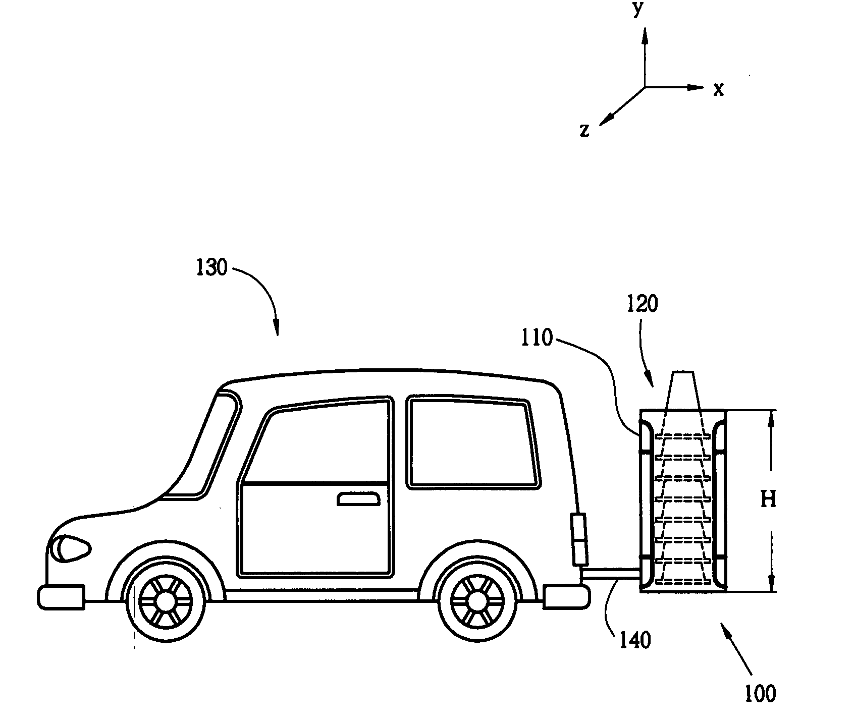
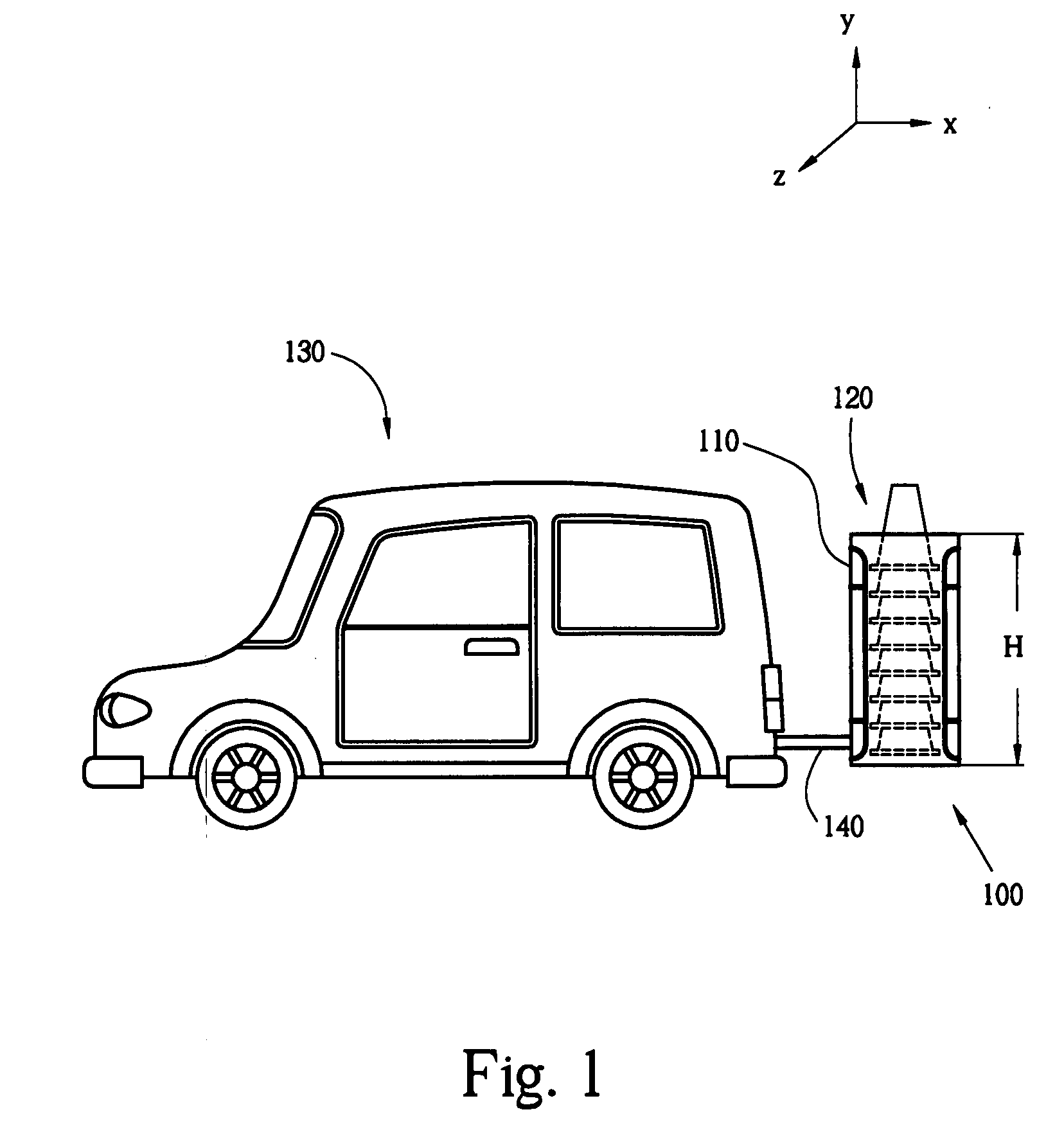
[0045] The present invention provides a device, method and system for automatically placing a safety cone to a desired position on a ground surface from a moving vehicle. The key idea of the present invention is that there is a receptacle that holds a plurality of safety cones. A releasing means which is attached to the receptacle is controlled and advances the safety cones in an automatic and controlled fashion, one-by-one, to desired locations on a road, street, freeway, intersection, or the like.

[0046]FIG. 1 shows a device 100 that ...


PUM


Abstract

Automatic placement of safety cones from a moving vehicle is provided. The preferred safety cone would have a flexible cone part. A receptacle holds a plurality of safety cones either with the flexible cone part in non-compressed position or in spring-loaded position. The receptacle is removably attached to the vehicle. A releasing means that is attached to the receptacle is controlled and advances the safety cones in an automatic and controlled fashion, one-by-one, to different locations on a ground surface from a moving vehicle.

Description

CROSS-REFERENCE TO RELATED APPLICATIONS [0001] This application is a continuation of copending U.S. patent application Ser. No. 10 / 871,191 filed Jun. 18, 2004. U.S. patent application Ser. No. 10 / 871,191 is a continuation-in-part of U.S. Pat. No. 6,752,582 with issue date of Jun. 22, 2004, which claims priority from a U.S. Provisional Patent Application 60 / 378,874 filed on May 7, 2002, all of which are incorporated herein by reference. [0002] U.S. patent application Ser. No. 10 / 871,191 also claims priority from a U.S. Provisional Application 60 / 486,782 filed Jul. 11, 2003, which is incorporated herein by reference. [0003] U.S. patent application Ser. No. 10 / 871,191 further claims priority from a pending U.S. patent application Ser. No. 10 / 131,316 filed Apr. 23, 2002 (U.S. Pat. No. 6,766,760 issued Jul. 27, 2004), which claims priority from U.S. Provisional Patent Applications No. 60 / 351,557 filed Jan. 23, 2002 and No. 60 / 360,141 filed Feb. 22, 2002, all of which are incorporated her...

Claims


Application Information

Patent Timeline
Patent Type & Authority Applications(United States)
IPC IPC(8): B60P1/00E01F9/012E01F9/70
CPCE01F9/014E01F9/0122E01F9/688E01F9/654E01F9/70
Inventor GARCIA, GUADALUPE C.
Owner WORLDWIDE SAFETY
Why Eureka
Try Eureka