
Thermoelectric personal environment appliance

a technology of personal environment and thermostat, applied in the field of air conditioning, can solve the problems of unfavorable individualized climate control, unfavorable air quality improvement, and high cost of occupied conditioning areas, and achieve the effect of adjusting the personal environment of a user

Inactive Publication Date: 2008-12-18
GENTHERM INC
View PDF67 Cites 68 Cited by
  • Summary
  • Abstract
  • Description
  • Claims
  • Application Information

AI Technical Summary

Benefits of technology

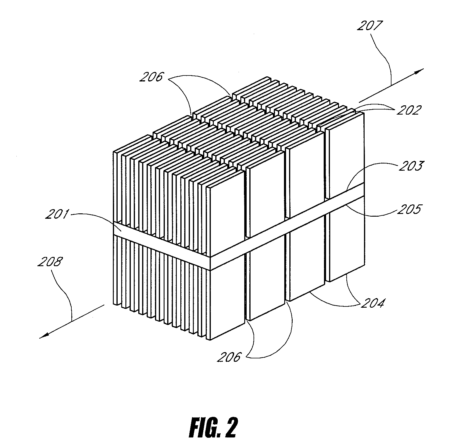
[0010]In certain embodiments, a method adjusts the personal environment of a user. The method comprises providing an appliance comprising an outlet vent configured to output conditioned air. The vent comprises a plurality of first tubular conduits generally parallel to one another. Each first tubular conduit has a length generally along the first tubular conduit, a width in a direction generally perpendicular to the first tubular conduit, and a ratio of the length divided by the width. The vent further comprises a plurality of second tubular conduits generally paral...

Problems solved by technology

This situation results in high costs of conditioning areas that are not occupied and also forces areas within a single controlled zone to accept that climate output whether or not it satisfies an individual's preference or sense of comfort.
Further, such control over large zones is not uniform, so that some individuals present in the zone are exposed to areas that are too hot while others are too cold.
Compressor-based systems for individualized climate control are impractical because of their size, cost, and noise output.
Such systems are not suitable for most practical work or dwelling situations.

Method used


Image

  • Thermoelectric personal environment appliance
  • Thermoelectric personal environment appliance
  • Thermoelectric personal environment appliance

Examples


Embodiment Construction

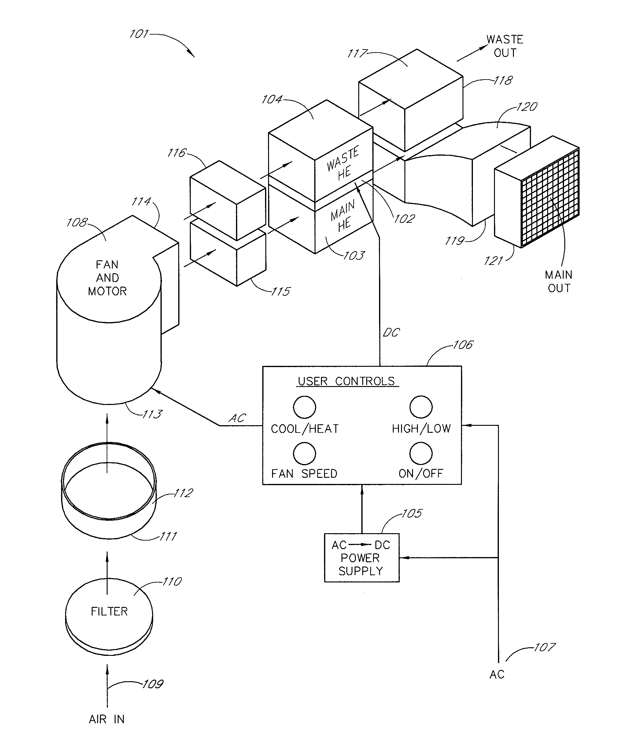
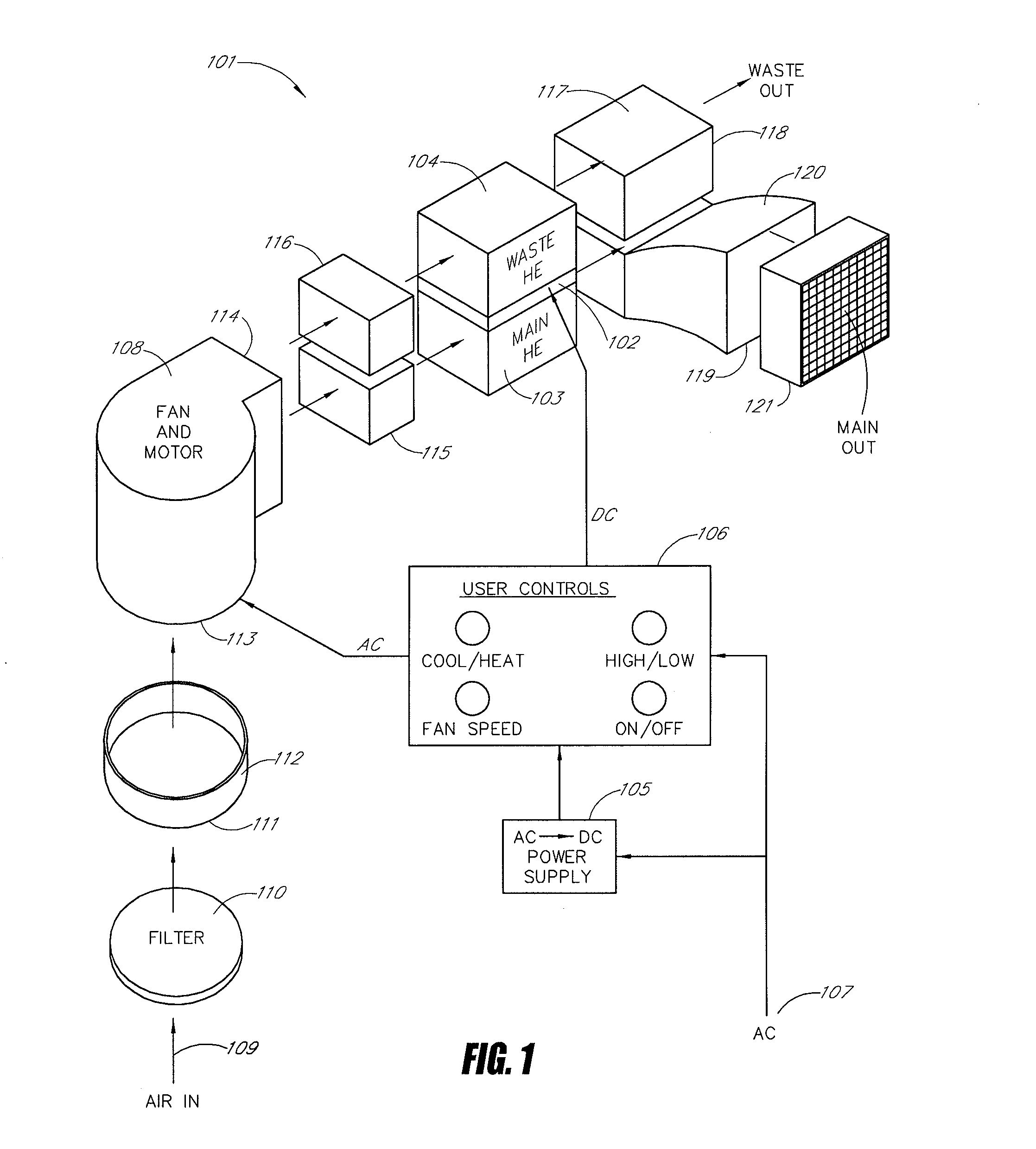
[0029]Certain embodiments described herein advantageously provide localized personal comfort to individuals with a range of controllability built into a device that is not intrusive to them or obstructive to their normal work or other environment. In certain embodiments, localized control for the temperature in the proximate vicinity of one or more individuals is provided. Such embodiments are distinguished from mobile cooling systems, such as individually cooled and heated seats, which more directly cool or heat the seat occupant as opposed to the local environment. In certain embodiments, the local workspace environment is controllable.

[0030]Certain embodiments described herein advantageously augment a personal environment appliance with additional features useful to an individual and synergistic with its fundamental design. Such features include localized air filtration, small area lighting, beverage heating / cooling, small personal refrigerator, and calming auditory environment.

[...


PUM


Abstract

A personal environment appliance and a vent for a personal environment appliance are provided. The appliance includes at least one thermoelectric module over at least one inlet port. The appliance further includes at least one main outlet port spaced from the at least one inlet port and at least one waste outlet port spaced from the at least one inlet port. The appliance further includes at least one filter between the at least one inlet port and the at least one thermoelectric module. The vent includes a plurality of first tubular conduits generally parallel to one another and each first tubular conduit having a ratio of the length divided by the width, The vent further includes a plurality of second tubular conduits generally parallel to one another and having a ratio of the length divided by the width. The plurality of second tubular conduits generally surrounds the plurality of first tubular conduits. The ratios of the second tubular conduits are sufficiently large such that air flow from the second tubular conduits is substantially laminar.

Description

CLAIM OF PRIORITY[0001]The present application is a continuation-in-part of U.S. patent application Ser. No. 10 / 215,163, filed Aug. 7, 2002, which is incorporated in its entirety by reference herein and which claims the benefit of priority to U.S. Provisional Patent Application No. 60 / 310,565, filed Aug. 7, 2001, which is incorporated in its entirety by reference herein. The present application claims the benefit of priority to U.S. Provisional Patent Application No. 60 / 942,945, filed Jun. 8, 2007, which is incorporated in its entirety by reference herein.BACKGROUND[0002]1. Field of the Invention[0003]The present application relates generally to conditioning of air by heating and / or cooling the air and, more particularly, is concerned with providing individualized, localized thermal comfort.[0004]2. Description of the Related Art[0005]Generally, where work places or dwellings are climate controlled, the climate control is provided by large compressor-based systems to large zones enc...

Claims


Application Information

Patent Timeline
IPC IPC(8): F25B21/02F25D17/06F25B39/02F24F7/04F24F3/16F24F5/00F25B21/04F25D31/00H01L35/00
CPCF24F5/0042F24F2221/38F25B21/04F25B2321/0251F25D31/007H01L35/00H10N10/00
Inventor BELL, LON E.DILLER, ROBERT W.PARK, DARRELL
Owner GENTHERM INC
Learn More