Top entry swing check valve

a check valve and swing technology, applied in the field of valves, can solve the problems of seat retainer pins being essentially chemically welded, seized or frozen in place, and add significant cost to the processes that require check valve control

Inactive Publication Date: 2008-12-18
STUNKARD GERALD A
View PDF5 Cites 52 Cited by
  • Summary
  • Abstract
  • Description
  • Claims
  • Application Information

AI Technical Summary

Benefits of technology

[0010]It is another feature of the present invention to provide a novel swing check valve mechanism that employs a bonnet alignment pin that is fixed to the valve body at the bonnet opening and is received by an alignment pin receptacle of the bonnet closure, thus providing for efficient positioning of the bonnet and the pivotally movable swing check member as the bonnet closure is assembled to the valve body.
[0012]The valve body defines an access opening of sufficiently large internal dimension that the seat assembly and swing check member can be inserted into or removed from the valve chamber via the access opening. A bonnet member is releasably retained in sealed engagement with the valve body and forms a closure for the access opening. Seat retainer pins are fixed to the bonnet member and extend into over-size holes or passages that are defined in an internal swing check member support structure that is an integral part of the valve body. When the bonnet member is in place, inner ends of the seat retainer pins are positioned immediately adjacent to or in contact with the annular seat retainer flange of the seat assembly and prevents the seat assembly from being moved out of its seat recess.
[0013]The bonnet member also defines a bonnet alignment hole that receives a bonnet alignment pin that is fixed to and projects upwardly from the valve body. The bonnet alignment hole is also over-size in relation to the dimension of the alignment pin to facilitate ease of bonnet assembly. The bonnet alignment pin ensures that the bonnet is properly aligned with respect to the valve body so that the seat retainer pins will be easily inserted through the seat retainer holes of the valve body and into seat retaining position with respect to the seat retainer flange of the valve seat assembly.

Problems solved by technology

This requires the maintenance of an inventory of serviceable valves and adds significant cost to the processes that require check valve control.
However, since threaded seats and seat recesses add somewhat to the complexity and cost of manufacturing a swing check valve mechanism, and since threaded valve seats are often very difficult to remove from their seat recesses, it is desirable to provide swing check valves having replaceable, non-threaded types of seats that are simply positioned within the seat recesses.
It is quite obvious from the disclosure of the '548 patent that fouling by the corrosive effects of the fluid being handled can cause the seat retainer pins to be essentially chemically welded, seized or frozen in place.
When such conditions exist it can be extremely difficult or impossible to remove the seat retainer pins from their seat retaining positions.
While the valve mechanism is designed for in-line repair, if the seat retainer pins cannot be removed under field repair conditions, it may be necessary to remove the valve body from the flow line and transport it to a repair facility.
This would require undesired labor costs and cause significant down time of the flow line, thus detracting from the intended use and commercial feasibility of the swing check valve product.

Method used


Image

  • Top entry swing check valve
  • Top entry swing check valve
  • Top entry swing check valve

Examples


Embodiment Construction

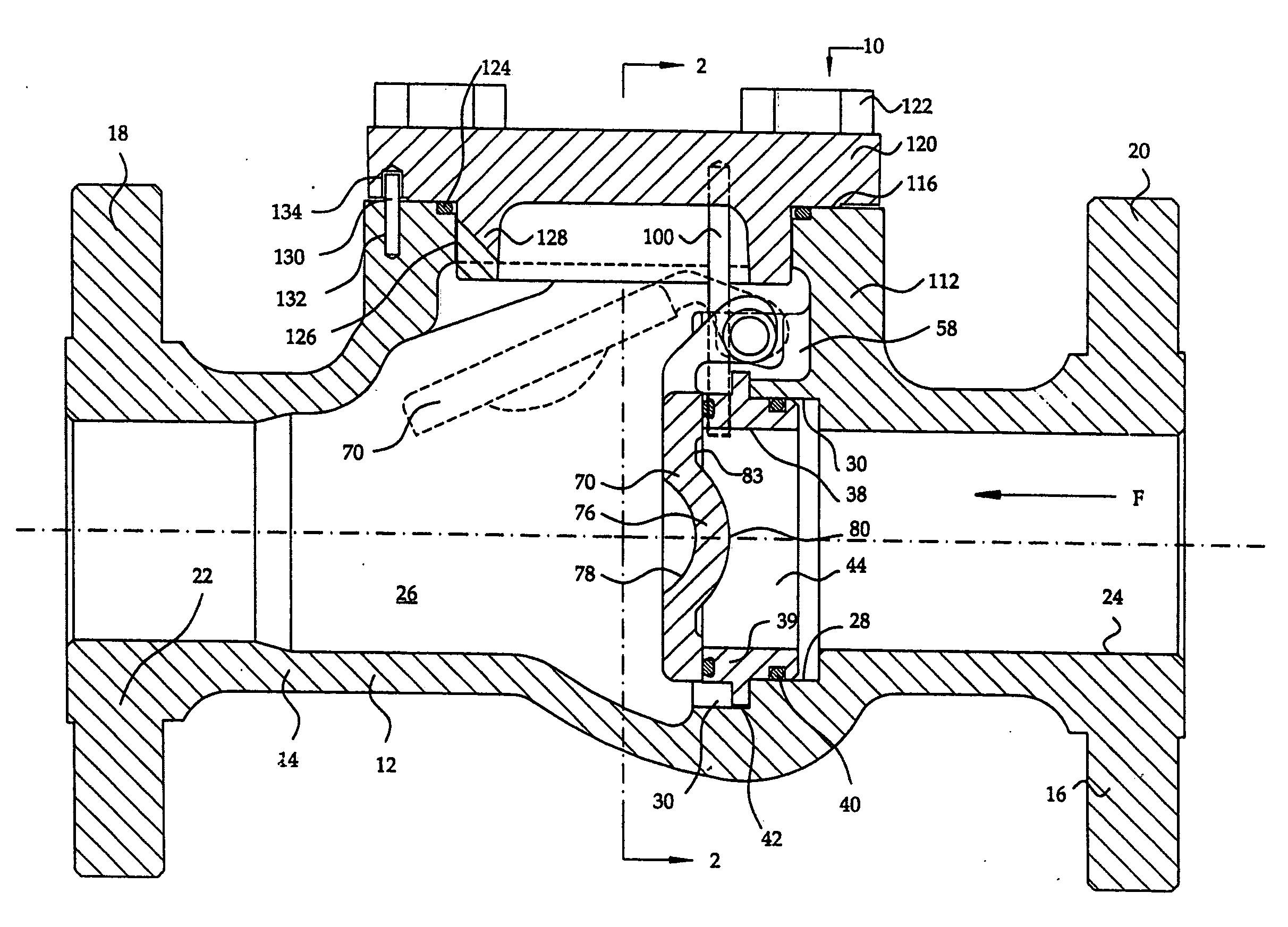
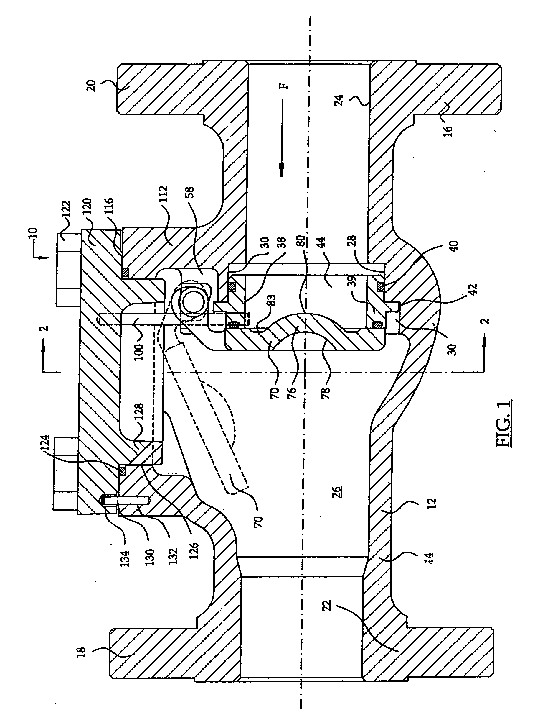
[0029]Referring now to the drawings and first to FIGS. 1 and 2, a swing check valve mechanism is shown generally at 10 and comprises a valve body 12 having tubular connection members 14 and 16 each being provided with connection flanges 18 and 20 or other suitable means for connecting the valve mechanism into a flow line. The tubular connection members and connection flanges define internal flow passages 22 and 24 each communicating with a valve chamber 26 defined by the valve body 12 and communicating with the flow line within which the valve mechanism is connected.

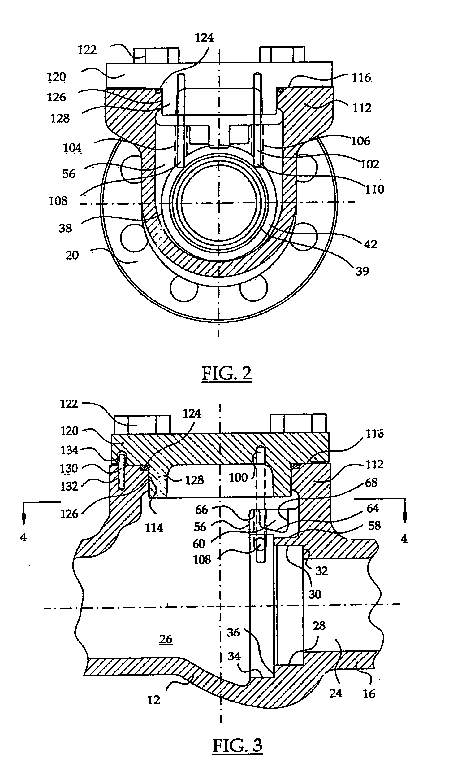
[0030]With reference to FIGS. 1 and 3, within the valve body a circular seat recess 28 is defined by the valve body 12 and is located in substantially concentric relation with the flow passage 24. The seat recess is formed in part by a cylindrical surface 30 having intersection with an annular seat recess shoulder 32 and includes a concentric enlarged section 34 having an annular shoulder 36.

[0031]An annular valve seat a...


PUM


Abstract

A top entry in-line repairable swing check valve having a valve body adapted for connection within a flow-line and having flow passages and a valve chamber and further defining a seat recess at the juncture of a flow passage and the valve chamber. A removable seat assembly within the seat recess establishes sealing with the valve body. A swing check member is pivotal within the valve chamber between an open position permitting flow through the flow passages and a closed position in sealing engagement with the seat assembly. The valve body has an access opening to the valve chamber of sufficient dimension for movement of the seat assembly and the swing check member therethrough. A bonnet closure for the access opening supports seat retainer pins positioned in seat retaining relation with the seat assembly. A bonnet orienting pin projects from the valve body and is received by an orienting hole of the bonnet to align the bonnet and seat retainer pins with respect to the valve body.

Description

BACKGROUND OF THE INVENTION[0001]1. Field of the Invention[0002]The present invention relates generally to valves for controlling the flow of fluids including liquids and gases and concerns swing check valves. More particularly, the present invention concerns a top entry swing check valve having a valve body defining an internal seat recess and having one or more seat retaining pins that are fixed to a removable bonnet defining a removable closure for the valve body. The seat retaining pins function to secure a check valve seat within a seat recess of the valve body. A bonnet orienting pin is employed to ensure proper positioning of the bonnet member relative to the valve body and also ensuring proper positioning of the seat retaining pins relative to the seat member. The present invention also concerns a alternative swing check valve construction that effectives lends itself to check valve mechanisms having a pivotally supported member carrying an annular sealing element which esta...

Claims


Application Information

Patent Timeline
Patent Type & Authority Applications(United States)
IPC IPC(8): F16K15/03
CPCF16K15/03F16K27/0209Y10T137/6086
Inventor STUNKARD, GERALD A.
Owner STUNKARD GERALD A
Why Eureka
Try Eureka