
Free Angled Implant Driver and Free Angled Hole Implant Abutment

Inactive Publication Date: 2008-12-18
LEE JONG HO
View PDF6 Cites 11 Cited by
  • Summary
  • Abstract
  • Description
  • Claims
  • Application Information

AI Technical Summary

Benefits of technology

[0014]If we use the free angled driver (301) and free angled hole abutment (300). In case of maxillay anterior teeth, we can move the screw hole to lingual surface of prosthesis (511). we can make esthetic and convenient prosthesis capable of screwing and unscrewing easily.
[0015]Also, posterior teeth, if use free angled hole abutment, we can move occlusal hole to the ideal position. There are many benefits in the function and the beauty.
[0016]Also, Screw-Cement-Retained-Prosthesis can make a epochal development due to this inventions.

Problems solved by technology

In addition, for cement type, residual cement in the gingival pocket can be harmful for gingival health.
It is too small to bear heavy torque.
And thus, technique is difficult to make prosthesis and expensive.
Lateral force can be produced in screwing tightly this lingual screw, therefore sometimes, screw and lingual screw breakage and implant failure will occur.
But hole position of this prosthesis is occasionally unaesthetic, it is hard to use in anterior teeth, and the more in posterior teeth.
But in anterior, also unaesthetic problem are existing.
And that, UCLA type prosthesis has a same problem to screw type.

Method used


Image

  • Free Angled Implant Driver and Free Angled Hole Implant Abutment
  • Free Angled Implant Driver and Free Angled Hole Implant Abutment
  • Free Angled Implant Driver and Free Angled Hole Implant Abutment

Examples


Embodiment Construction

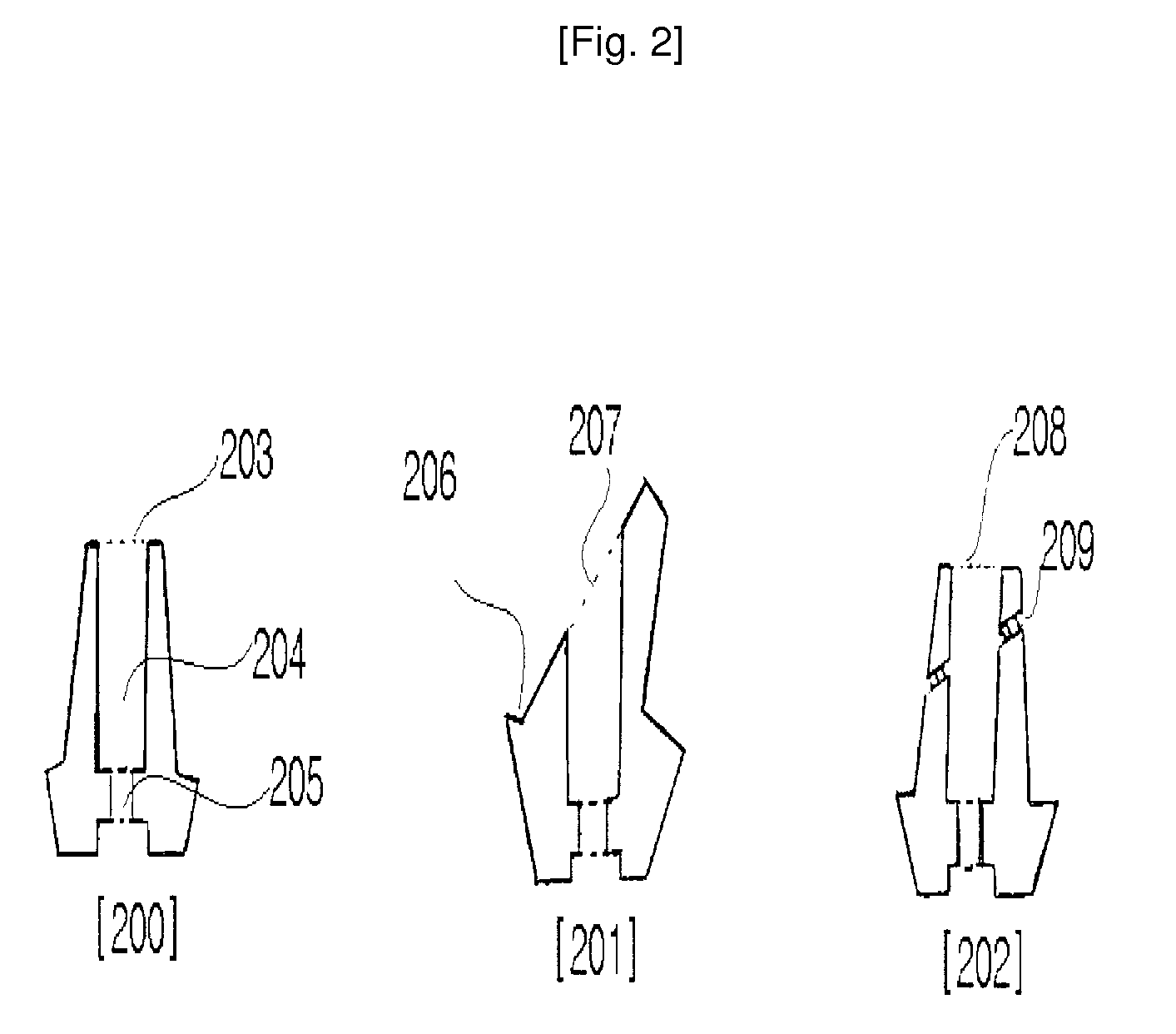
[0113]As illustrated in FIG. 3, The free angled implant driver has a torque transmission part (309) which can be consisted with 1 to 10 piece in number, and will be located within 10 mm from the working end of driver (310).

[0114]The free angled hole abutment (300) with the free angled implant driver (301), has the entrance of screw inserting hole (306) which is located apart from central axis line of abutment screw (606), at a distance

MODE FOR THE INVENTION

[0115]The free angled implant driver (301) used for implant, are consist of a driver handle (308) or a handpiece-type connection (1002) of a power axis (312), a torque transmission part (309) delivering the rotation power from the driver handle along the driver's axis (313), a driver part of working axis (310) performing a work.

[0116]Torque transmission part is a combination of a loop, a gear, a wire, or a tube.

[0117]FIG. 3 is a diagram of free angle driver with loops type angle portion (309). If the handle is rotated, the loops t...


PUM


Abstract

In case of straight driver (100), The entrance of screw inserting hole of Implant prosthesis is on the same line with implant fixture's axis. Due to this position of the hole, final prosthesis has many difficulties. Thus. I invented the free angled driver (301). For maxillay anterior teeth, we can move the screw hole to lingual surface of prosthesis (511). we can make esthetic and convenient prosthesis with capability of easy screwing and unscrewing. Also. I invented the free angled hole abutment (300) for the free angled implant driver (301), so we can move occlusal hole to the ideal position. It is an epoch-making change to solve many problems in the contemporary dental implant prosthetics.

Description

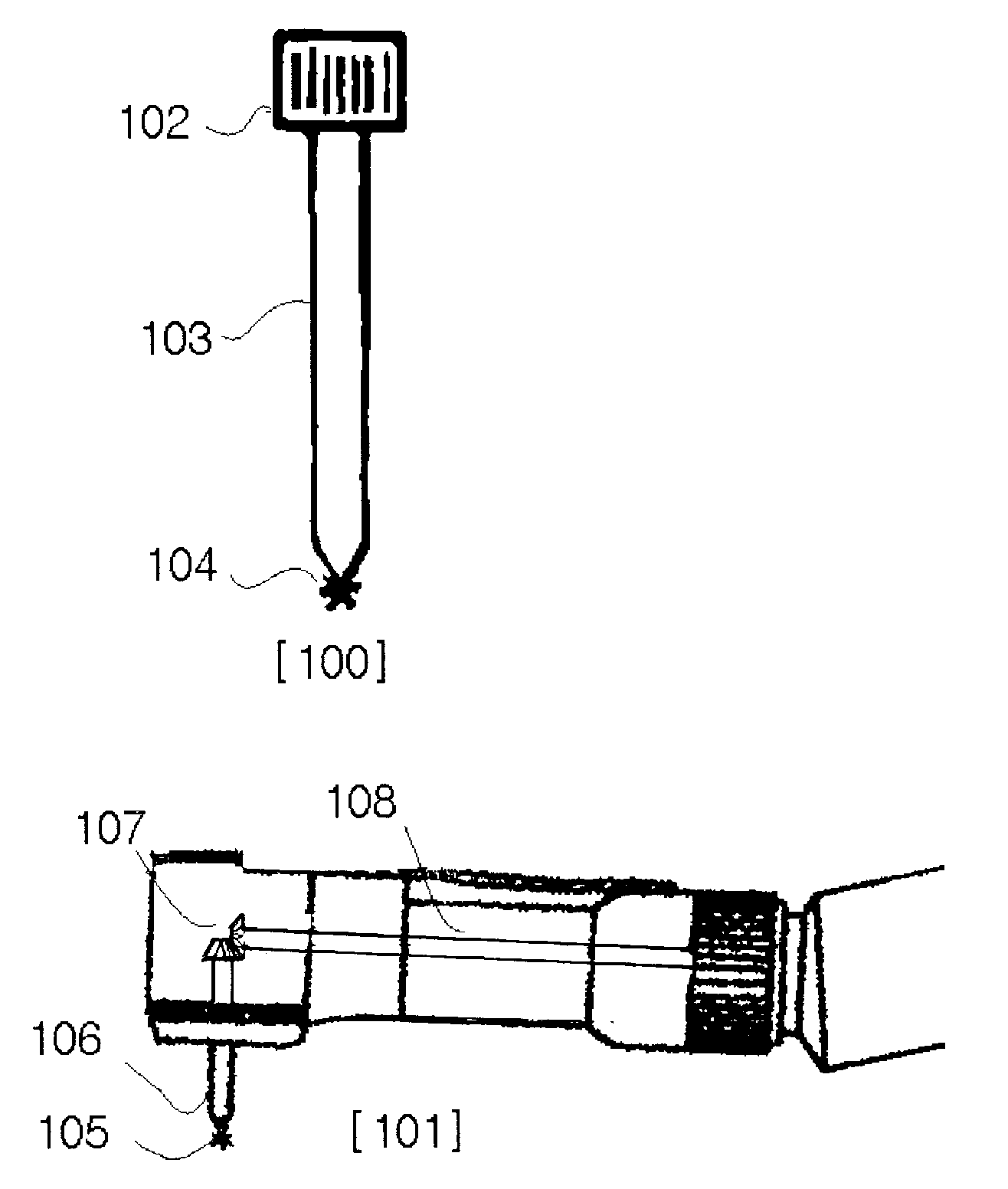
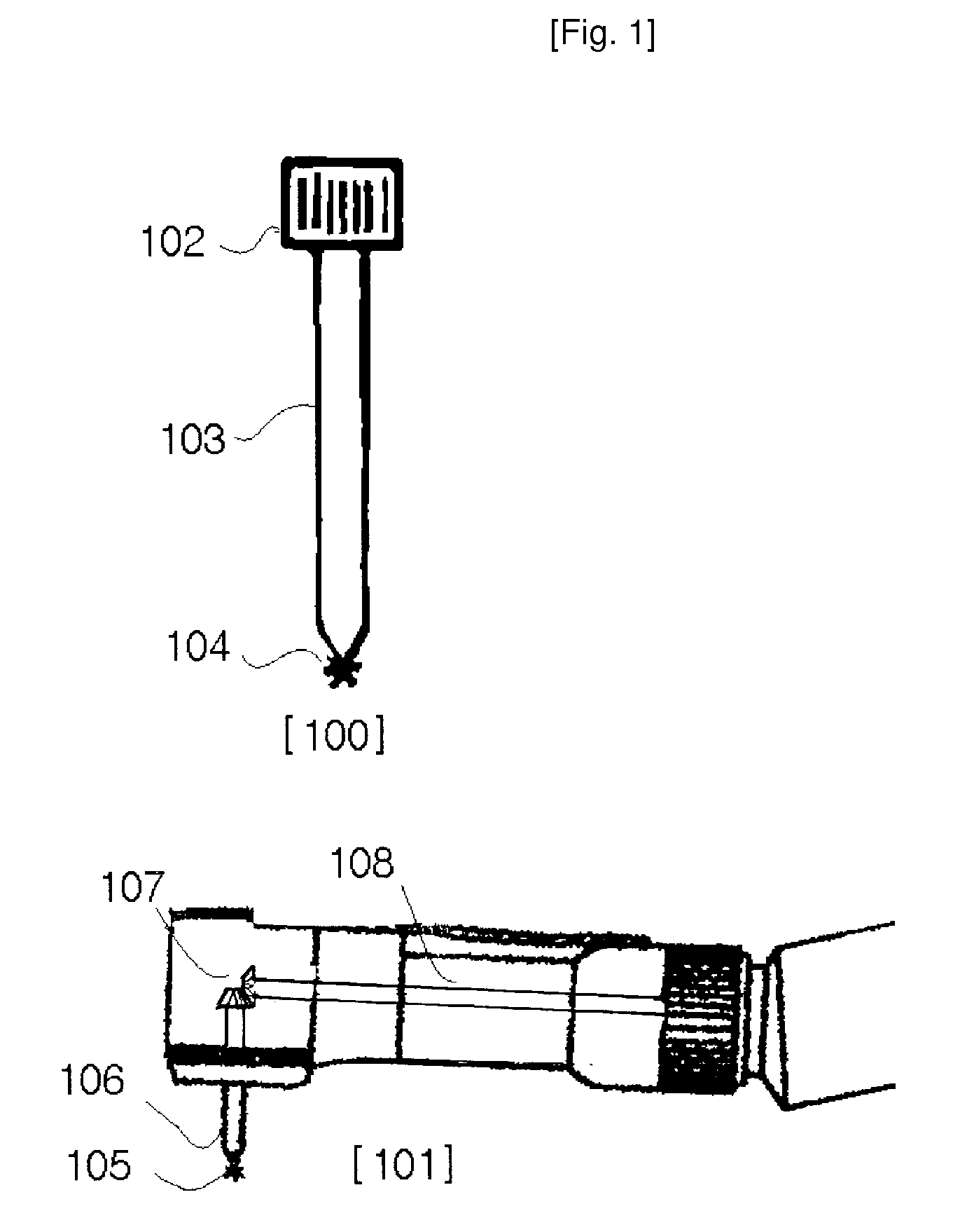
TECHNICAL FIELD[0001]Dental implant becomes a important part of contemporary dentistry. Dental implant is composed of three components, implant fixture (508) which is a implanted part in the bone; implant abutment (506) which is connected with implant fixture by screw; tooth shape prosthesis which is attached with implant abutment.[0002]In most cases, when a implant abutment is fixed to implant fixture, a abutment screw (507) is screwed into a implant fixture by driver. In this case, the central axis of driver body, the central axis of implant abutment screw, and the central axis of implant fixture are all in one straight line. At this point of time, two types of driver was developed. One is the straight driver (100) and the other is the right angle driver system (101). The right angle driver system is useful when the patient can't open the mouth widely. This system has two components; driver shaft (106) and a driver edge (105). Driver shaft meets with it's driver handle at right an...

Claims


Application Information

Patent Timeline
IPC IPC(8): A61C3/02A61C8/00
CPCA61C1/12A61C8/005A61C8/0068A61C8/0089B25B17/00A61C8/00
Inventor LEE, JONG HO
Owner LEE JONG HO
Learn More