
Display device calibration system

a display device and calibration system technology, applied in the field of display devices, can solve the problems of unsatisfactory attempt to replace ccfl light sources with led light sources along one or more edges of such larger display screens, and the current led technology is untenable, particularly with respect to led brightness or light output, and the difficulty of achieving the effect of reducing the number of display devices

Inactive Publication Date: 2008-12-25
APPLE INC
View PDF3 Cites 15 Cited by
  • Summary
  • Abstract
  • Description
  • Claims
  • Application Information

AI Technical Summary

Problems solved by technology

The technical challenges are modest because the screens are modest in size, so that the individual display pixels are never very far from one or more of the LED light sources.
On the other hand, the larger geometries of typical flat panel computer monitors and displays (e.g., larger than about 20 inches) create area-to-perimeter ratios that have proven untenable for current LED technologies, particularly with respect to LED brightness or light output.
This has meant that it has proven unsatisfactory to attempt to replace CCFL light sources with LED light sources along one or more edges of such larger display screens.
Accordingly, such displays continue to employ CCFL light sources even though CCFL light sources are increasingly less desirable than LED light sources.
Prior attempts to do so, however, have proven unsatisfactory.
Attempts to meet these criteria in acceptable form factors and costs have been unsuccessful.
Previous efforts to achieve these objectives have failed due to a number of practical obstacles.
For example, even though LED light outputs have dramatically improved in recent years, a very large number of LEDs is still required to provide sufficient brightness in such larger displays.
This then requires an enormously large maze of wires and / or bulky circuit boards to mount, support, and power such a large number of LEDs in a distributed matrix configuration.
The resulting structure is bulky, thick, heavy, and not well suited for managing and removing the heat that is generated by the LEDs and the underlying electrical circuitry.
It is also expensive and not well suited for efficient manufacturing.
Another challenge with utilizing LEDs in large arrays is maintaining uniformity of color in the large numbers of LEDs.
Understandably, reducing or compensating for such variability increases cost and complexity significantly as the number of LEDs increases in larger display configurations and environments.
The difficulties in providing proper thermal management capability can readily lead to temperature variations across the distributed array of LED light sources.
Since the color qualities of LED light sources are sensitively dependent upon their operating temperatures, such non-uniformities lead to unacceptable variations in color from one portion of the display to another.
Another major obstacle to commercialization of such larger LED light source displays is the complexity and costs associated with measuring and calibrating each such display as it is being manufactured.
Calibration of the TFT-LCD to compensate for LED variability can be complex due, among other reasons, to the properties of the TFT-LCD itself.
Heretofore this has been a time-consuming and expensive process, acceptable perhaps for limited-production, “high-end” specialty displays, but not acceptable for mass-produced consumer products.
As a result, prior efforts to replace CCFL light sources with LEDs in commercial consumer applications have largely failed to move beyond the prototype stage.
Prior attempts to utilize LEDs in large displays have thus not solved the problem of building displays that are light, easy and inexpensive to manufacture, uniform in color, low in cost, and that also provide the excellent overall high quality user experience that customers demand and expect.
Solutions to these problems have been long sought but prior developments have not taught or suggested any solutions and, thus, solutions to these problems have long eluded those skilled in the art.

Method used


Image

  • Display device calibration system
  • Display device calibration system
  • Display device calibration system

Examples


Embodiment Construction

[0034]The following embodiments are described in sufficient detail to enable those skilled in the art to make and use the invention. It is to be understood that other embodiments would be evident based on the present disclosure, and that system, process, or mechanical changes may be made without departing from the scope of the present invention.

[0035]In the following description, numerous specific details are given to provide a thorough understanding of the invention. However, it will be apparent that the invention may be practiced without these specific details. In order to avoid obscuring the present invention, some well-known circuits, system configurations, and process steps are not disclosed in detail.

[0036]Similarly, the drawings showing embodiments of the system are semi-diagrammatic and not to scale and, particularly, some of the dimensions are for the clarity of presentation and are exaggerated in the drawing FIGS. Likewise, although the views in the drawings for ease of de...


PUM


Abstract

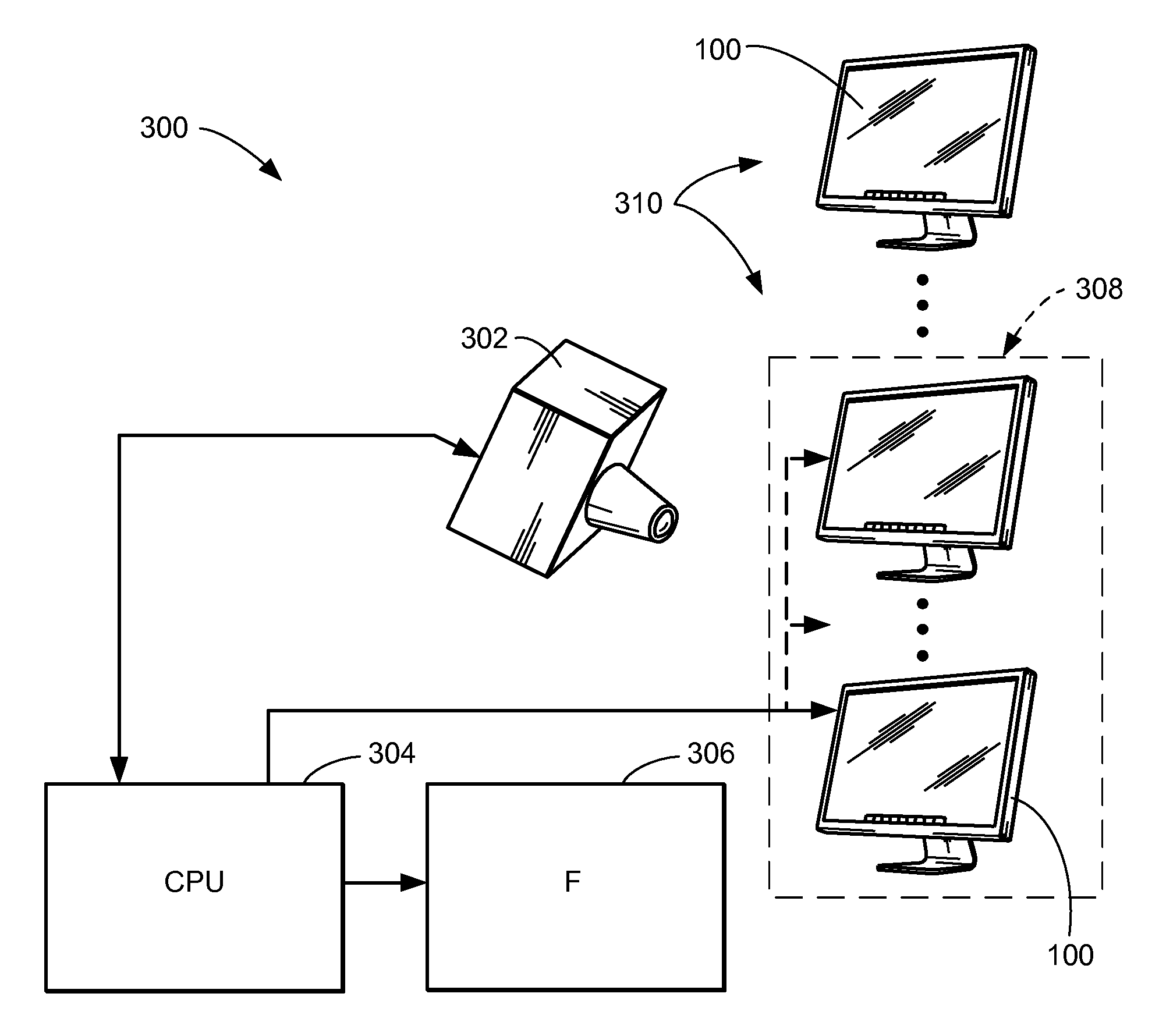
A display device calibration system is provided. The overall color response of a display family is characterized, and the idiosyncratic color response characteristics of the display family are determined. The idiosyncratic color response characteristics of the display family are related to respective idiosyncratic color response points. Individual idiosyncratic color response point values for an individual member of the display family are determined. The color response of the individual member of the display family is specified from the individual idiosyncratic color response point values of the individual member of the display family and the overall color response of the display family.

Description

TECHNICAL FIELD[0001]The present invention relates generally to display devices, and more particularly to a reduced measurement display device calibration system.BACKGROUND ART[0002]With the advance of display systems illumination technology from incandescent to fluorescent to solid-state light sources, and with ever-increasing miniaturization, one popular electronic category seems not to have kept pace. That category is large-sized personal data displays, such as personal computer monitors.[0003]For many years, such monitors were based on cathode ray tube (“CRT”) technology. More recently, flat panel displays have increasingly displaced CRT displays. The most common form of flat panel displays utilizes one or more fluorescent light sources located behind a liquid crystal display (“LCD”) screen. Contemporary technology has enabled the use of cold cathode fluorescent light (“CCFL”) light sources, but because a cathode emitter is still required, a high voltage source for striking and ...

Claims


Application Information

Patent Timeline
IPC IPC(8): G09G5/02
CPCG09G3/006G09G2320/0233G09G2320/0666G09G2320/0693G09G2360/145
Inventor MARCU, GABRIEL G.CHEN, WEI
Owner APPLE INC
Learn More