Firearm

a technology for firearms and receivers, applied in the field of firearms, can solve the problems of requiring long manufacturing times, requiring significant assembly effort, and affecting the safety of users, etc., and achieves the effect of reducing the risk of users, and reducing the cost of production

Inactive Publication Date: 2009-01-01
RMDI
View PDF48 Cites 89 Cited by
  • Summary
  • Abstract
  • Description
  • Claims
  • Application Information

AI Technical Summary

Benefits of technology

[0012]In some configurations, the upper receiver and its guidance feature and passageway are formed by extrusion. Additionally, the upper receiver may include a second passage way that is formed as the upper receiver is extruded. Extrusion permits the formation of multiple features in one processing step, which can minimize machining and assembly time and reduce manufacturing costs. For example, the upper receiver may be extruded with an accessory rail that extends parallel to the longitudinal axis. In some configurations, the accessory rail may be extruded at the 3, 6, 9, & 12 o'clock positions.
[0030]In some configurations, the ejector of the firearm may be attachable to the receiver at a plurality of locations. Having an ejector that is removably attachable to the receiver at a plurality of locations permits the firearm to accommodate different cartridge sizes. Specifically, adjusting the position of the ejector affects how a spent cartridge is ejected from the firearm.

Problems solved by technology

Currently available firearms have many limitations that can potentially place a user at risk, require long manufacturing times, or be expensive to produce.
For example, receivers for firearms that include guidance features, such as internal rails, within a passageway tend to require significant effort to assemble.
Currently available firearms also present serious safety issues where water is able to fill a barrel or a squib round is fired and the bullet fails to exit the barrel.
In these situations, the pressures within the chamber may lead to mechanical failure of the firearm.
A mechanical failure at or near the location of the extractor can render a firearm useless.
In a combat situation, a useless firearm places the user at great risk.
Thus, the spent cartridge may give away the position of the user to an enemy during combat.
However, these firearms all use the same size ejection port for each caliber, which may lead to problems with ejection.
For example, the ejection port may be too large so that the spent cartridge is ejected in a random pattern.
This random ejection pattern may lead to lost brass as well as user frustration as the brass may be ejected rearward into the user of the firearm.
Where the ejection port is functional but slightly too small, the spent cartridge may fail to entirely eject from the firearm which may raise reliability issues.
Similarly, firearms that are able to fire different calibers of cartridges use the same ejector in the same location for all calibers, which can also lead to ejection problems with certain calibers or entirely prevent a firearm designed to fire one caliber from firing larger or smaller cartridges.
For example, the ejector for a firearm designed to fire a 5.56 NATO cartridge may be unable to fire a Springfield 30.06 cartridge because the ejector is disposed too close to the barrel.
Currently available firearms for use with multiple calibers may also be difficult to take apart for cleaning or modification.
Currently available firearms may also require relatively long periods of time to change from one caliber to another.

Method used


Image

  • Firearm
  • Firearm
  • Firearm

Examples


Embodiment Construction

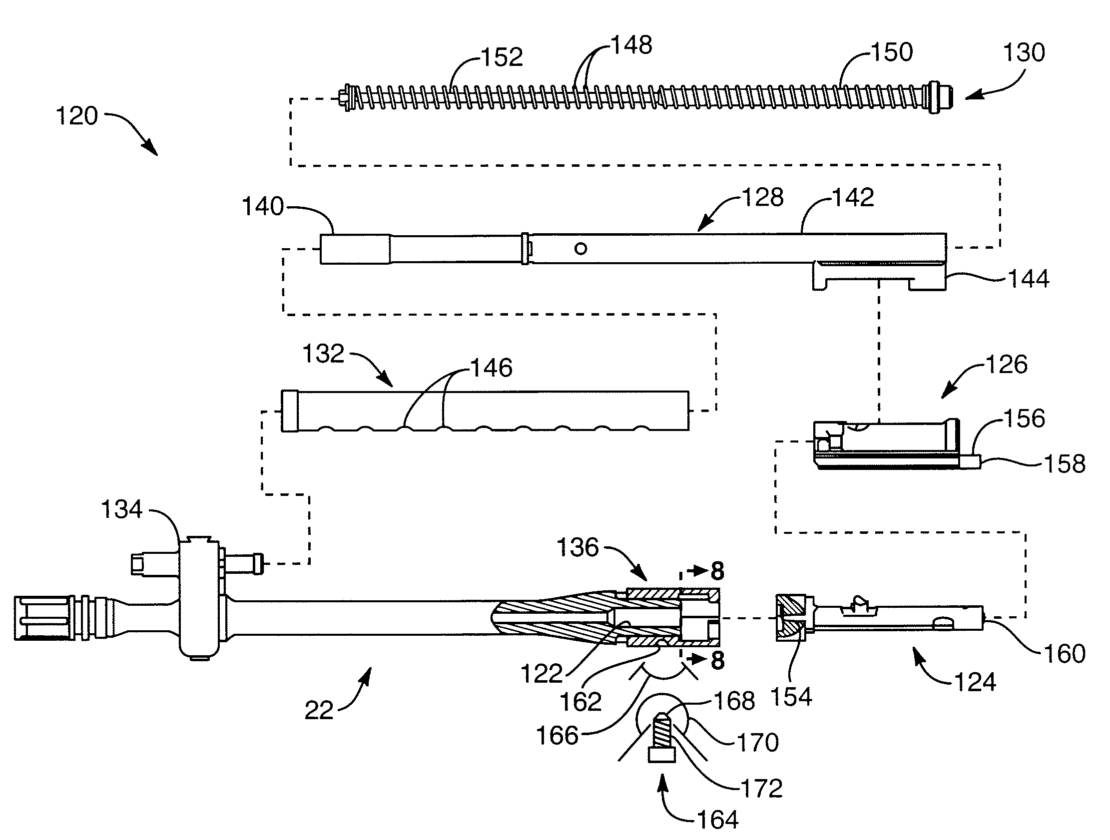
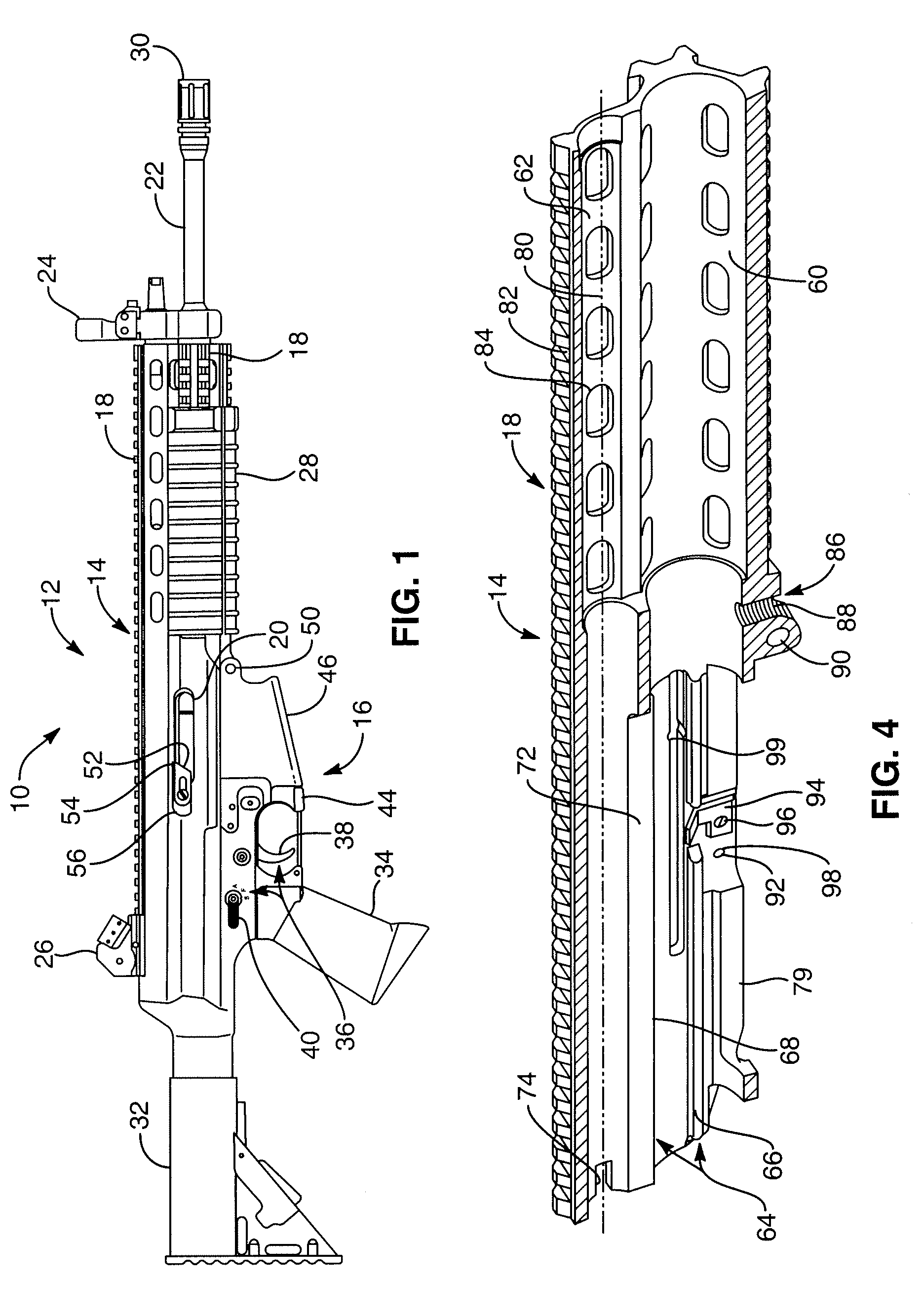
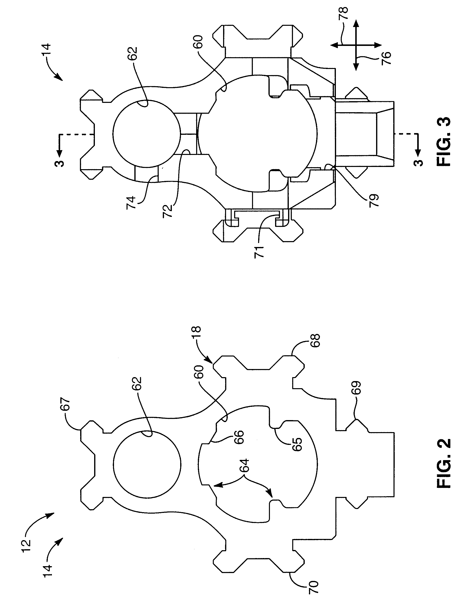
[0053]The presently preferred embodiments of the present invention will be best understood by reference to the drawings, wherein like parts are designated by like numerals throughout. It will be readily understood that the components of the present invention, as generally described and illustrated in the figures herein, could be arranged and designed in a wide variety of different configurations. Thus, the following more detailed description of the embodiments of the improved firearm of the present invention, as represented in FIGS. 1 through 14, is not intended to limit the scope of the invention, as claimed, but is merely representative of presently preferred embodiments of the invention.

[0054]For this application, the phrases “connected to,”“coupled to,” and “in communication with” refer to any form of interaction between two or more entities, including mechanical, electrical, magnetic, electromagnetic, and thermal interaction. The phrase “attached to” refers to a form of mechani...


PUM


Abstract

A firearm including a bolt for securing a barrel such that the barrel attaches to a receiver with increased repeatability at the same location. The bolt included a tapered end and may also include a threaded section. The receiver comprises a barrel attachment feature which allows the bolt to pass through and can also include threads for engaging the bolt. The barrel comprises a beveled recess for engaging the tapered end of the bolt. The angle of the tapered end and the beveled recess are approximately reciprocal. The bolt passes through the receiver and its tapered end engages the beveled recess to secure the barrel to the receiver.

Description

RELATED APPLICATIONS[0001]This utility application is a divisional of and claims priority to U.S. patent application Ser. No. 11 / 055,580 filed Feb. 10, 2005, entitled FIREARM, which claims the benefit of U.S. Provisional Application No. 60 / 544,586, filed Feb. 13, 2004, entitled IMPROVED FIREARM, and also claims the benefit of U.S. patent application Ser. No. 10 / 911,963, filed Aug. 4, 2004, entitled MULTI-CALIBER AMBIDEXTROUSLY CONTROLLABLE FIREARM, all of which are hereby incorporated herein by reference.BACKGROUND OF THE INVENTION[0002]The present invention relates to firearms. More specifically, the present invention relates to firearms that can be quickly configured with a minimum of additional parts to fire different calibers of ammunition with improved reliability in harsh environmental and firing conditions.[0003]Currently available firearms have many limitations that can potentially place a user at risk, require long manufacturing times, or be expensive to produce. For exampl...

Claims


Application Information

Patent Timeline
Patent Type & Authority Applications(United States)
IPC IPC(8): F41A21/00F41A3/36F41A5/12F41A5/18F41A11/00F41A15/14F41A17/00F41A17/42F41A17/76F41A19/43
CPCF41A3/26F41A3/36F41A3/70F41A5/12F41A5/18F41A21/485F41A11/00F41A15/14F41A17/42F41A17/76F41A19/43F41A5/24F41A3/66
Inventor ROBINSON, ALEXANDER J.NEBEKER, DARIN G.HOLWAY, JON C.
Owner RMDI
Why Eureka
Try Eureka