Optical elements having variable power prisms

a technology of variable power prisms and optical elements, applied in the field of corrective optical prismatic devices, can solve problems such as diplopia, asthenopia, and difficulty reading, and achieve the effects of reducing the number of optical prismatic devices

Inactive Publication Date: 2009-01-01
THE RES FOUND OF STATE UNIV OF NEW YORK
View PDF2 Cites 16 Cited by
  • Summary
  • Abstract
  • Description
  • Claims
  • Application Information

AI Technical Summary

Benefits of technology

[0010]Aspects of the present invention can equalize differential prismatic effects of right and left eye lenses over their entire aperture in aniso- and anti-metropia. In addition, aspects of the invention can provide constant prescribed therapeutic prism power across the lens aperture by offsetting the prismatic effect of a lens in the absence of anisometropia. Moreover, aspects of the invention can provide a variation in prism power for vision training in strabismus, head trauma, etc. conditions.
[0011]Aspects of the present invention address the above limitations of prior art prisms and prior art prism and lens combinations. According to aspects of the invention, a variable power or progressive power Fresnel prism is provided. One aspect of the invention maintains a substantially constant prism correction for binocular vision conditions, as such, diplopia and strabismus. Aspects of the invention are intended for correction of vision imbalance and in use in vision training and therapy. In one aspect, a prism is provided having a prism power that varies across its aperture to offset the prismatic effect of the lens. According to aspects of the invention, the variation in prismatic power of the present invention can provide an effective correction to the differential prismatic effects of the two lenses that occur with anisometric lens corrections when the eyes turn. By supplementing or replacing a conventional refractive or Fresnel prism with an aspect of the invention, when prisms are prescribed for therapeutic purposes, the desired prism power can be provided, for example, across the entire aperture of the lens and prism combination.
[0015]Another aspect is an optical element comprising a plurality of integral prism facets having varying prismatic effect. In one aspect, the plurality of facets comprises a first plurality of facets having a base-down prismatic effect and a second plurality of facets having a base-up prismatic effect. In another aspect, the first plurality of prism facets is positioned above an optical center of the element and the second plurality of prism facets is positioned below the optical center of the element or the first plurality of prism facets is positioned below an optical center of the element and the second plurality of prism facets is positioned above the optical center of the element. In one aspect, the absolute value of the prismatic effect of the first plurality of prism facets and the second plurality of prism facets increases with a distance from an optical center of the device. In a further aspect, the optical element further comprises a third plurality of prism facets having a substantially constant prismatic effect.

Problems solved by technology

Vertical imbalances also are induced by differential prismatic effects of anisometropic lens corrections by excursions downward of the lines of sight of the eyes from the optical centers.
This may result in diplopia, asthenopia, dizziness, and difficulty reading.
Consequently, the combination of the prism and lens may fail to provide the prescribed therapeutic prismatic correction throughout the range of mobility of the eyes.
As a result, the eyes incur a hyperphoria at the reading level.
Hyperphorias greater than about 1.5 prism diopters can have adverse effects on binocular vision.
When such fixed power prisms are used in combination with a patient's lens prescription, the prescribed prism power is limited to a line of sight through the optical center of the lens.

Method used


Image

  • Optical elements having variable power prisms
  • Optical elements having variable power prisms
  • Optical elements having variable power prisms

Examples


example 1

[0044]As an example of the details and benefits of aspects of the invention. The following analysis and calculations are provided. The calculation of vertical imbalances caused by differential prismatic effects due to anisometropia when eyes turn downward to read can be calculated based upon the following assumptions:[0045]Given: Spherical lenses.[0046]Right eye distance lens Rx. F=−4.00 diopters[0047]Left eye distance lens Rx F=−1.00 diopters[0048]Lines of sight intersect lenses 1.0 cm below the optical centers of the lenses.

Note that in the following calculations, the above parameters this will be converted to a decentration (d) of the lens, therefore, d=+1.0 cm. In other words, decentering a negative lens up, introduces a base-down effect that is equivalent in prism diopters to turning the eyes downward.

[0049]According to Prentice's rule, the prismatic effect, PeΔ, of a lens is given by

PeΔ=d×F

where d=distance from optical center (in cm), provided above, and F=dioptric power of t...

example 2

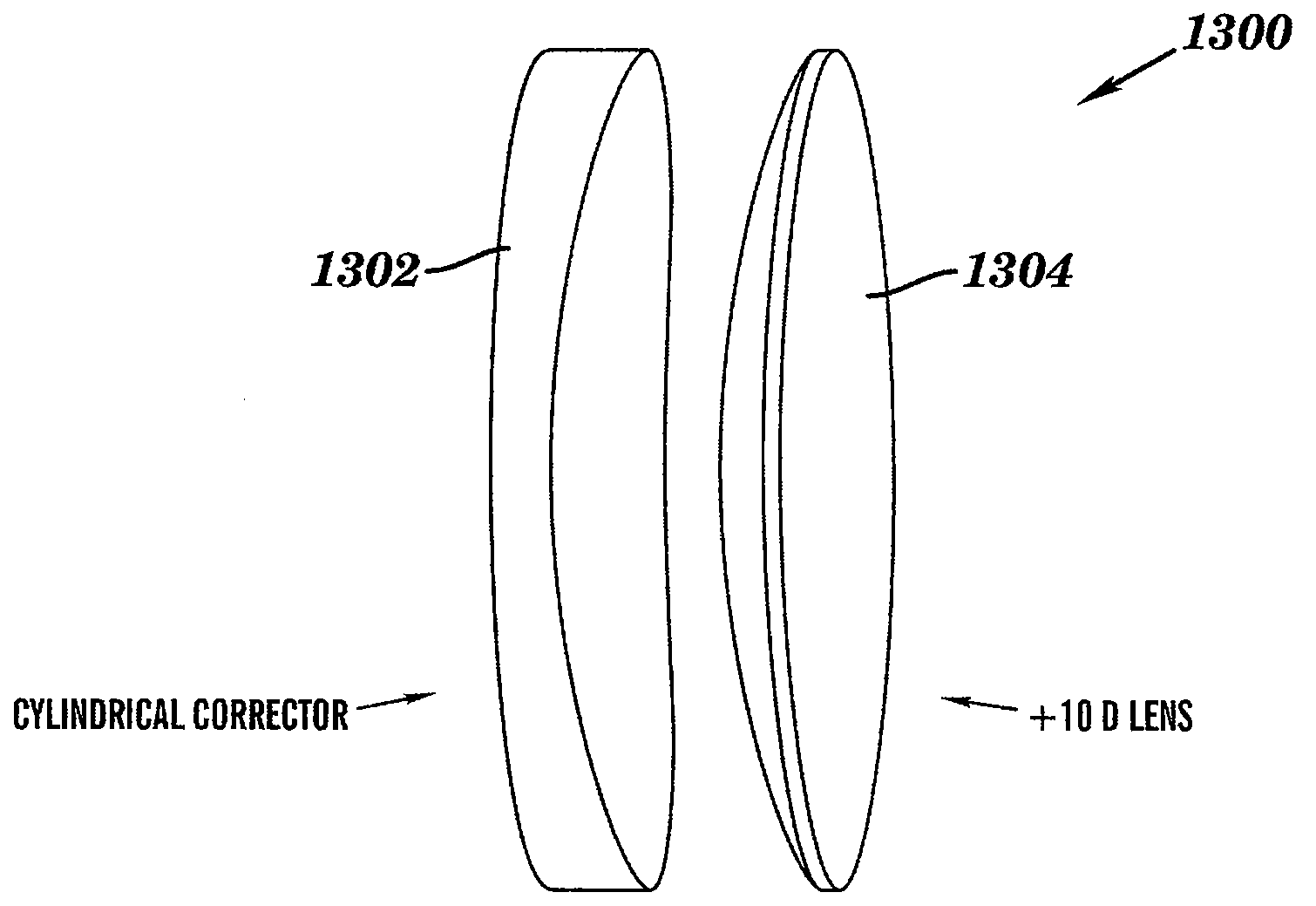
[0053]In this example, the anisometric patient in Example 1 develops a strabismus that requires a +10Δ base-up prism in front of the right eye to restore single binocular vision. In this case it is necessary to correct the anisometropic, Pe, as in Example 1 and to add the +10Δ base up (BU) to design a combined variable power prism (VPP) as shown in the last column of Table B below.

TABLE Bd (cm)ΔPeΔ (RE − LE)VPP (RE)TherapeuticTotal VPP (RE)2.0−6.0Δ BD+6.0Δ BU+10.0Δ BU+16.0Δ BU1.0−3.0Δ BD+3.0Δ BU+10.0Δ BU+13.0Δ BU0.0 0.0 0.0+10.0Δ BU+10.0Δ BU−1.0+3.0Δ BU−3.0Δ BD+10.0Δ BU +7.0Δ BU−2.0+6.0Δ BU−6.0Δ BD+10.0Δ BU +4.0Δ BU

This example illustrates the use of a variable power prism to correct for the differential prismatic effects caused by the anisometropia and incorporate a therapeutic prism of 10Δ base-up for the right eye. FIG. 6 is another example of a representative plot, similar to the plot in FIG. 5, of the effect of one aspect of the invention. FIG. 6 summarizes the data in Table B ...

example 3

[0058]In this example, a calculation of vertical imbalances caused by differential prismatic effects due to anisometropia when eyes turn downward to read is provided. Specifically, the patient in Example 2 also has an astigmatism and requires 10Δ base-up for the right eye. In this calculation, the following assumptions are made:[0059]Given: Spherical lenses.[0060]Right eye distance lens Rx. F=−4.00 Dsph / −3.00 Dcyl axis 180 degrees[0061]Left eye distance lens Rx F=−1.00 Dsph / −1.00 Dcyl axis 135 degrees

The total vertical prismatic effect of the spherical (sph) and cylindrical (cyl) components is given again by Prentice's Rule:

Pe=dFsph+Fcyl(d sin θ cos θ)

The calculations for this example are summarized in Table C below

TABLE CdTotal VPP(cm)Pe (RE)Pe (LE)ΔPeΔ (RE − LE)VPP (RE)TherapeuticTotal VPP(LE)2−14.0−3.0−11.011.010.021.0 BU21.0 BD1−7.0−1.5−5.55.510.015.5 BU15.5 BD00.00.00.00.010.010.0 BU10.0 BD−17.01.55.5−5.510.0 4.5 BU 4.5 BD−214.03.011.0−11.010.0 −1.0 BD 1.0 BU

[0062]In the aspect...


PUM


Abstract

Optical elements having a plurality of integral prism facets having varying prismatic power are provided. These optical elements address the disadvantages of conventional therapeutic optical prisms by addressing the undesirable variation in prismatic effect that results when conventional prisms are combined with optical lenses in binocular vision. Specifically, the present invention can equalize differential prismatic effects of right and left eye lenses over their entire aperture. The optical elements may include a plurality of prism facets having base-down and base-up prismatic power. The elements may include individual elements having variable prismatic elements, individual elements combining both conventional prisms and variable prism, or separate elements having conventional prisms and variable prism. The plurality of integral facets or a substantially continuous smooth surface may be provided, for, example, a cylindrical surface having a circular or non-circular profile. Methods of correcting binocular vision are also disclosed.

Description

CROSS-REFERENCE TO RELATED APPLICATION[0001]This application claims priority from pending U.S. Provisional Patent Application 60 / 946,833, filed on Jun. 28, 2007, the disclosure of which is incorporated by reference herein in its entirety.BACKGROUND OF THE INVENTION[0002]1. Field of the Invention[0003]The present invention relates to corrective optical prismatic devices, and more particularly, to corrective optical prismatic devices employing varying prismatic effects to correct the undesirable variation in prismatic effect of conventional optical prismatic devices.[0004]2. Description of Related Art[0005]Clear single binocular vision requires the eyes to accommodate and converge on the object of regard. Among the conditions that interfere with fusional eye movements are strabismus, heterophorias, and heterotropias. Patients are most sensitive to vertical imbalances. These imbalances may be caused by the vertical component of strabismus, or anatomic factors. Vertical imbalances also ...

Claims


Application Information

Patent Timeline
Patent Type & Authority Applications(United States)
IPC IPC(8): G02C7/14G02B3/08G02B3/10G02C7/06
CPCG02C7/14
Inventor KATZ, MILTON
Owner THE RES FOUND OF STATE UNIV OF NEW YORK
Why Eureka
Try Eureka