Three-Dimensional Wiring Body for Mounting Electronic Component and Electronic Component Mounting Structure

a wiring body and electronic component technology, applied in the direction of printed circuit parts, circuit bendability/stretchability, laminated printed circuit boards, etc., can solve the problems of time-consuming and troublesome operations, the effect of reducing time-consuming operations and flexible adaptability to design changes

Inactive Publication Date: 2009-01-08
FURUKAWA ELECTRIC CO LTD
View PDF7 Cites 11 Cited by
  • Summary
  • Abstract
  • Description
  • Claims
  • Application Information

AI Technical Summary

Benefits of technology

[0016]According to the invention, the three-dimensional, electronic components mounted wiring body is comprises a flat wiring body, on which a plurality of electronic components is mounted and which is preformed with bends so as to be shaped into a three-dimensional structured flat wiring body which fits the shape of a base structure on which the flat wiring body is to be mounted. Thus, the present invention reduces the time-consuming operations that are required in the conventional art to individually mount and wire electronic components on the base structure at respective positions which is integrally formed in a complicated three dimension. In addition, the present invention can readily be adapted to a design change of the base structure by simply changing the shape of the three-dimensional structured flat wiring body, thus increasing the freedom of design,

Problems solved by technology

However, the above mentioned conventional art disclosed in the respective patent documents generally has two problems: The first problem is associated with the operability of the mounting and assembling.
In the case of patent documents D1 and D2, the light emitting structure using a wiring circuit in the form of electric wires or bus bars requires time-consuming and troublesome operations for mounting and wiring LEDs on a complicated and integrally formed, three-dimensional base of the structure.
Similarly in the case of patent documents D3 to D6, the light emitting structure using a flat wir

Method used


Image

  • Three-Dimensional Wiring Body for Mounting Electronic Component and Electronic Component Mounting Structure
  • Three-Dimensional Wiring Body for Mounting Electronic Component and Electronic Component Mounting Structure
  • Three-Dimensional Wiring Body for Mounting Electronic Component and Electronic Component Mounting Structure

Examples


Embodiment Construction

[0061]The present invention will now be described with respect to an embodiment thereof taken in conjunction with the drawings.

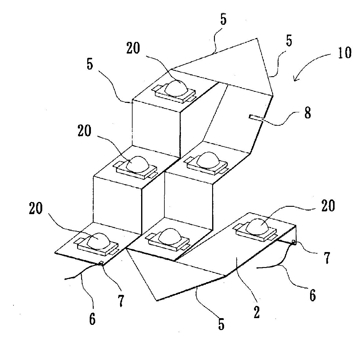
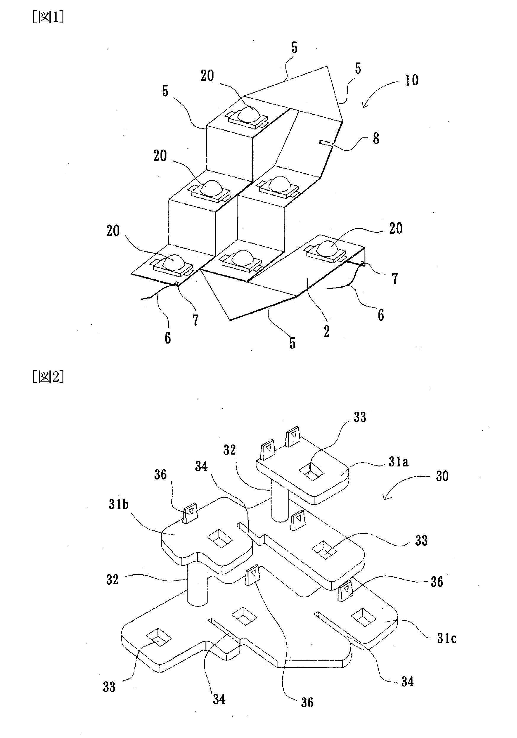
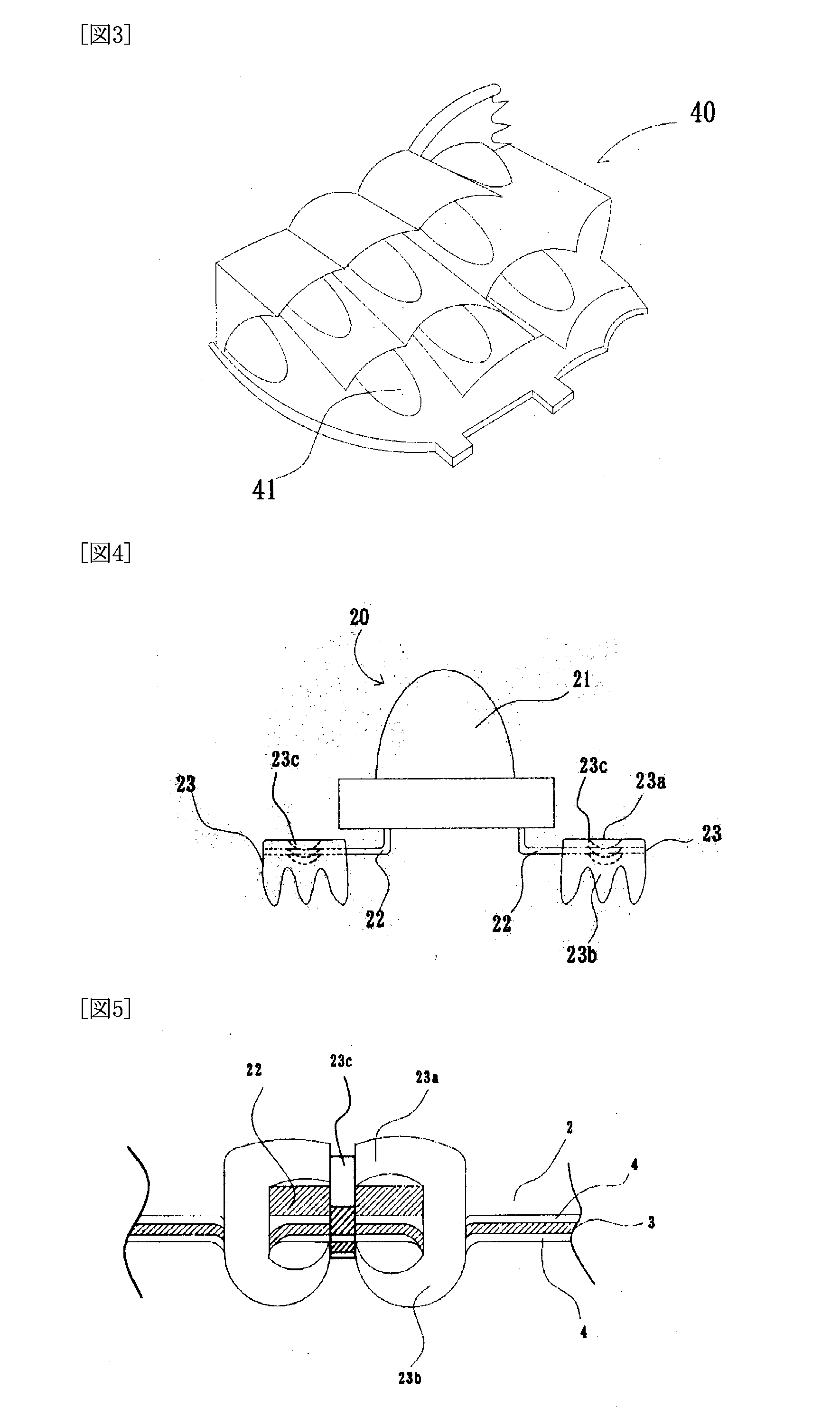
[0062]FIG. 1 is a perspective view of a three-dimensional structured flat wiring body 10 which is designed to constitute a three-dimensional, electronic components mounted wiring body according to an embodiment of the present invention. FIGS. 2 and 3 are presented to illustrate an electronic components mounting structure according to the embodiment of the invention. Specifically, FIG. 2 is a perspective view of a base structure 30 assembled from a plurality of base members 31. FIG. 3 is a perspective view of a reflector structure 40 on which is mounted the base structure 30 on which the three-dimensional, electronic components mounted wiring body 10 is mounted.

[0063]In the embodiment of the invention, the three-dimensional, electronic components mounted wiring body comprises a flat wiring body 2, on which a plurality of electronic components 20 is mounted, a...


PUM


Abstract

A three-dimensional, electronic components mounted wiring body comprises a flat wiring body, on which a plurality of electronic components is mounted, and which is preformed with bends to be configured into a three-dimensional structured flat wiring body which fits the shape of a base structure on which the flat wiring body is to be mounted. An electronic components mounting structure is provided by mounting the three-dimensional, electronic components mounted wiring body on the three-dimensional base structure which is assembled from base members and their joining members. Connectors having piercing members are used to electrically and mechanically connect the electronic components to the flat wiring body.

Description

TECHNICAL FIELD[0001]The present invention relates to a three dimensional wiring body for mounting and wiring electronic components for use in vehicles and others as well as an electronic components mounting structure.BACKGROUND ART[0002]In recent years, light emitting diodes (LEDs) have been widely used for lamps on the front and rear of automobiles. An electric wire, bus bar or flat wiring body has been used to form a wiring circuit or power feed circuit for such LEDs. For instance, a light emitting structure in which LEDs that are connected to electric wires are arranged in a three dimension and steps is known (see patent documents D1 and D2). Also known is another light emitting structure in which LEDs that are connected to a flat wiring body are arranged in three dimensional steps (see patent documents D3 to D6).Patent Document D1: Japanese Patent Application Publication 2000-243110Patent Document D2: Japanese Patent Application Publication 2002-245812Patent Document D3: Japane...

Claims


Application Information

Patent Timeline
IPC IPC(8): H05K1/00H01L33/00H01L33/48H01L33/54H01L33/56H01L33/60
CPCH05K1/0278H05K1/0393H05K1/189H05K3/0058H05K2203/302H05K2201/10106H05K2201/10651H05K2201/2009H05K2203/1189H05K3/326
Inventor ENOMOTO, NORITSUGUUTSUNOMIYA, HIROFUMIKAMIMURA, KENMOTOMURA, SHIGEKIAOYAGI, SHIGEHARUTAKEDA, JUNICHI
Owner FURUKAWA ELECTRIC CO LTD
Why Eureka
Try Eureka