Injection-molded gear

a technology of injection molding and gear, which is applied in the direction of hoisting equipment, applications, other domestic objects, etc., can solve the problems of adverse effect on gear strength, insufficient equalization of inability to accurately match the speed of molten resin flow

Active Publication Date: 2009-01-08
ENPLAS CORP
View PDF0 Cites 15 Cited by
  • Summary
  • Abstract
  • Description
  • Claims
  • Application Information

AI Technical Summary

Benefits of technology

[0018]The present invention is configured such that the resin flow regulating projections project from a side surface of the web. Therefore, regardless of the thickness of the web, the speed of the flow of molten resin injected into the cavity from the pin point gate can be equalized and the weld line formed on the merging section of the molten resin can be sufficiently reduced. As a result, the present invention can provide a high-strength, high-intensity injection-molded gear.

Problems solved by technology

When the weld line 56 is formed on the injection-molded gear 50, the weld line 56 not only has an adverse effect on tooth profile accuracy, but may also have an adverse effect on gear strength.
Therefore, the speed of the flow of molten resin cannot be sufficiently equalized.
The weld line formed at the section at which the molten resin merges cannot be sufficiently reduced.

Method used


Image

  • Injection-molded gear
  • Injection-molded gear
  • Injection-molded gear

Examples


Embodiment Construction

[0033]Embodiments of the present invention will be described in detail, below, with reference to the drawings.

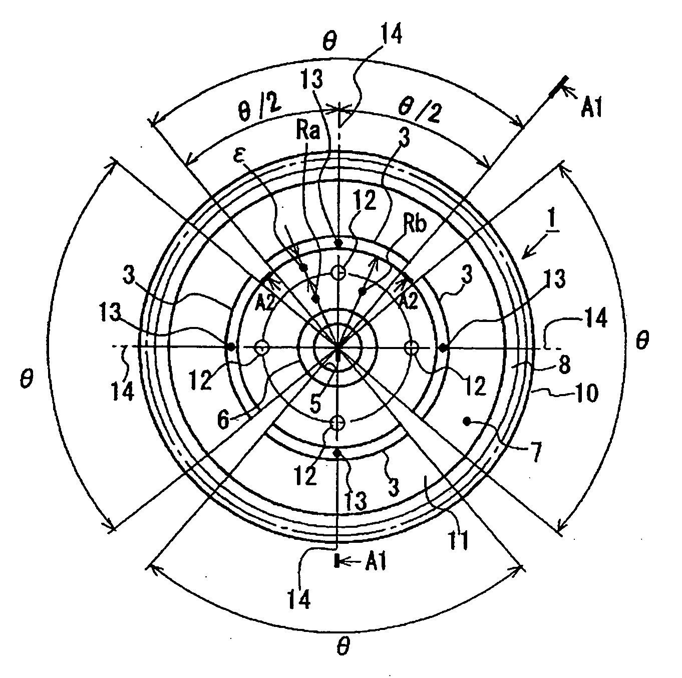
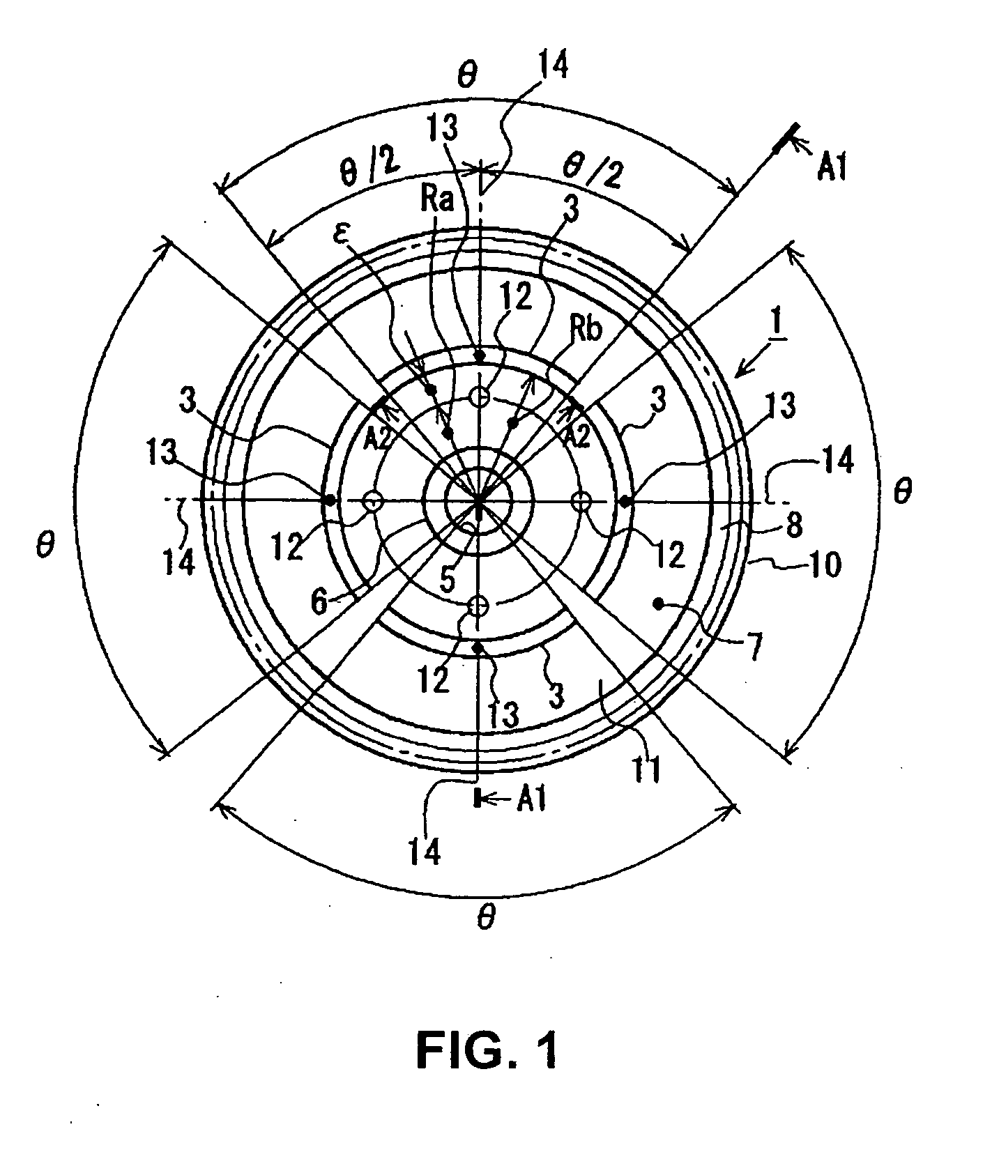
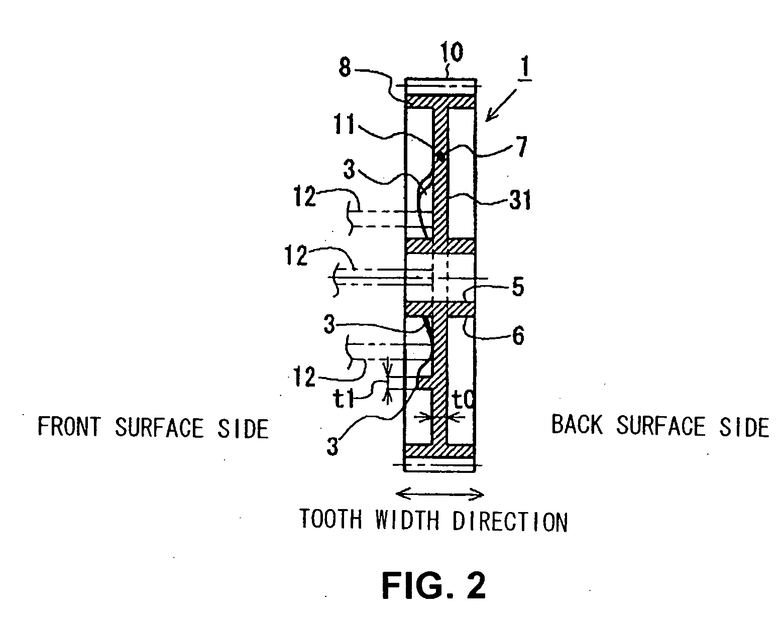
[0034]FIG. 1 to FIG. 3 show an injection-molded gear 1 according to an embodiment of the present invention. FIG. 4 is a cross-sectional view of a mold 2 used to manufacture the injection-molded gear 1 according to the embodiment. FIG. 1 is a front view of the injection-molded gear 1 according to the embodiment. FIG. 2 is an overall cross-sectional view of the injection-molded gear 1 taken along line A1-A1 in FIG. 1. FIG. 3 is a partial cross-sectional view of the injection-molded gear 1 taken along line A2-A2 in FIG. 1, in which a resin flow regulating projection 3 is enlarged.

[0035](Injection-Molded Gear)

[0036]The injection-molded gear 1 is formed by molten resin being injected into a cavity 4 of a mold 2. The molten resin is, for example, polyacetal, polyamide, polyphenylene sulfide, and polybutylene terephthalate (see FIG. 2 and FIG. 4).

[0037]As shown in FIG. 1 to FIG. 3,...


PUM

PropertyMeasurementUnit
thicknessaaaaaaaaaa
circumferenceaaaaaaaaaa
heightaaaaaaaaaa

Abstract

A high-strength, high-precision injection-molded gear is provided in which, regardless of the thickness of a web, the speed of flow of molten resin injected into a cavity from pin point gates can be equalized and a weld line formed in a merging section of the molten resin can be sufficiently reduced.
Resin flow regulating projections 3 that partially thicken a web 7 are formed in a position on a side surface 11 side of the web 7 between pin point gates 12 and a teeth section 8 such as to project from the side surface 11 of the web 7. The resin flow regulating projections 3 are formed such that a projection height is the highest on a radial direction line 14 extending from the pin point gates 12 in the outward radial direction and gradually decreases away from the position on the radial direction line 14 in a circumferential direction of the web 7.

Description

BACKGROUND OF THE INVENTION[0001]1. Field of the Invention[0002]The present invention relates to an injection-molded gear used in a power transmission device in various automobile components, industrial machineries, precision machineries, and the like.[0003]2. Description of the Related Art[0004]In recent years, an injection-molded resin gear (injection-molded gear) is often used in a gear train in automobile components, printers, and the like to achieve lighter weight, quieter operation noise, and the like. The automobile components, printers, and the like operate by receiving driving force from a drive source, such as a motor.FIRST CONVENTIONAL EXAMPLE[0005]FIG. 7 is a front view of an injection-molded gear 50 of a first conventional example. FIG. 8 is a cross-sectional view of the injection-molded gear 50 taken along line A3-A3 in FIG. 7. FIG. 9 is a cross-sectional view of a mold 51 of the injection-molded gear 50 shown in FIG. 7 and FIG. 8.[0006]The injection-molded gear 50 of ...

Claims


Application Information

Patent Timeline
Patent Type & Authority Applications(United States)
IPC IPC(8): B29C45/22
CPCB29C45/0025B29C45/0046B29C45/2708Y10T74/1987B29L2015/003Y10S74/10Y10T74/19851B29C2045/0049
Inventor HAGIHARA, TORU
Owner ENPLAS CORP
Why Eureka
Try Eureka