Disc Fusion Implant
a disc fusion and disc technology, applied in the field of disc fusion implants, can solve problems such as inability to move, and achieve the effect of reducing the rigidity of the second portion
- Summary
- Abstract
- Description
- Claims
- Application Information
AI Technical Summary
Benefits of technology
Problems solved by technology
Method used
Image
Examples
second embodiment
[0146]Referring to FIGS. 20-25, an implant strip may include different types of deflecting portions. Additionally, an implant strip may or may not include motion limiting tabs. In a second embodiment, seen in FIGS. 20-21, second implant strip 2030 includes first deflecting ellipse 2032, second deflecting ellipse 2034 and third deflecting ellipse 2036 disposed between edges 2002 and 2006 and within interior space 2038. Preferably, ellipses 2032, 2034 and 2036 are joined to edges 2002 and 2006. As axial force 2028 is applied, deflecting ellipses 2032, 2034 and 2036 are compressed until they obtain a substantially circular shape. At this point, ellipses 2032, 2034 and 2036 are disposed against one another, which may prevent any further deflection or deformation in the axial direction.
third embodiment
[0147]In a third embodiment, shown in FIGS. 22-23, third implant strip 2040 includes fourth deflecting ellipse 2042 and fifth deflecting ellipse 2046 disposed between edges 2002 and 2006 and within interior space 2048. Preferably, ellipses 2042 and 2046 are joined to edges 2002 and 2006. In addition, third implant strip 2040 preferably includes cross bar 2044 that is disposed between fourth deflecting ellipse 2042 and fifth deflecting ellipse 2046. Cross bar 2044 preferably connects to both lower edge 2002 and upper edge 2006. In a preferred embodiment, deflecting ellipses 2042 and 2046 as well as cross bar 2044 may all deflect under axial force 2028. In particular, cross bar 2044 may experience column deflection. Preferably, cross bar 2044 only partially deflects, which limits the axial motion of lower edge 2002 and upper edge 2006.
fourth embodiment
[0148]In a fourth embodiment, seen in FIGS. 24-25, fourth implant strip 2050 includes first curved portion 2052 and second curved portion 2056. Preferably, curved portions 2052 and 2056 are joined to edges 2002 and 2006. Fourth implant strip 2050 also preferably includes motion limiting tabs 2054. As axial force 2028 is applied to fourth implant strip 2050, curved portions 2052 and 2056 may deflect in the axial direction. Preferably, as tabs 2054 make contact, the deflection of lower edge 2002 towards upper edge 2006 may cease. Additionally, curved portions 2052 and 2056 may contact edges 2002 and 2006, preventing further deflection.
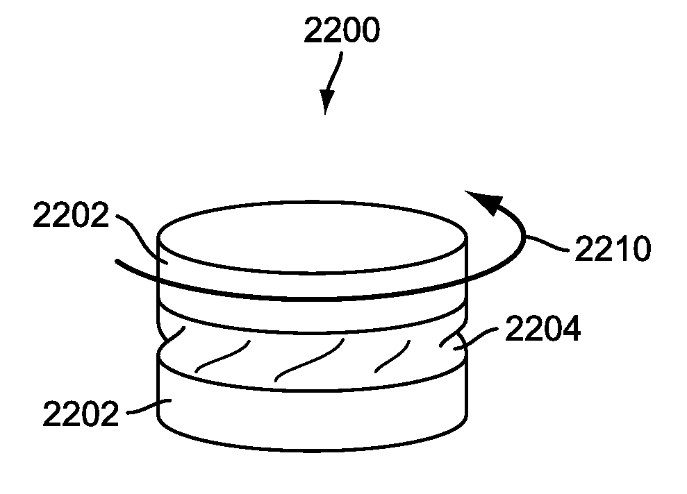
[0149]FIGS. 26-28 illustrate another preferred embodiment of implant strip 2300 that is configured for axial deflection. Implant strip 2300 includes upper side 2304 and lower side 2306 that extend vertically. Protruding portion 2303 preferably extends outwards from, and is preferably joined with, upper side 2304 and lower side 2306. In particular, protru...
PUM
| Property | Measurement | Unit |
|---|---|---|
| width W1 | aaaaa | aaaaa |
| width W1 | aaaaa | aaaaa |
| length L1 | aaaaa | aaaaa |
Abstract
Description
Claims
Application Information
 - R&D Engineer
- R&D Manager
- IP Professional
- Industry Leading Data Capabilities
- Powerful AI technology
- Patent DNA Extraction
Browse by: Latest US Patents, China's latest patents, Technical Efficacy Thesaurus, Application Domain, Technology Topic.
© 2024 PatSnap. All rights reserved.Legal|Privacy policy|Modern Slavery Act Transparency Statement|Sitemap


