Spinal implant with porous and solid surfaces

a technology of solid surface and implant, which is applied in the field of spinal surgery, can solve the problems of degeneration, bulging, thinning and abnormal movement, and the difficulty of implant manufacturing, and achieve the effect of facilitating the insertion of the implant and reducing the stiffness of the implan

Active Publication Date: 2016-07-14
STRYKER EURO OPERATIONS HLDG LLC
View PDF5 Cites 96 Cited by
  • Summary
  • Abstract
  • Description
  • Claims
  • Application Information

AI Technical Summary

Benefits of technology

[0008]Other embodiments according to the first aspect may include a nose having a solid exterior, a hollow area and a porous region. At least one serration may be included on each of the upper and lower surfaces. The serration(s) may include a solid tip, a solid root and a porous section. The implant may further include first and second side walls extending between the upper and lower surfaces, the side walls including a solid exterior surface and a porous interior surface. The first and second side walls may each include lateral windows. The lateral windows may reduce the stiffness of the implant and may be tapered. The implant may also include a threaded opening at a rear end Implants according to the present invention may be constructed of any material suitable for implantation in the body of a patient, for instance, a metal such as titanium. The implants can be configured for insertion from various aspects, e.g., a posterior approach, a lateral approach or an anterior approach. The implant may include a nose that facilitates the insertion of the implant in a first orientation and rotation to a second orientation. The implant may be constructed from an additive manufacturing process, and may be machined to create smooth surfaces.

Problems solved by technology

Typical disc issues include, inter alia, degeneration, bulging, herniation, thinning and abnormal movement.
Although there is little doubt that the bone growth into the implant is beneficial in maintaining an implant in place, these implants are often very difficult (and thusly, expensive) to manufacture.
Additionally, existing implants that implement porous material do so in a limited manner Often times, because of manufacturing or strength concerns or the like, the porous material is limited to a thin layer covering the upper and lower surfaces of the implant, which only allows for a small amount of bone to grow into the implant.

Method used


Image

  • Spinal implant with porous and solid surfaces
  • Spinal implant with porous and solid surfaces
  • Spinal implant with porous and solid surfaces

Examples


Embodiment Construction

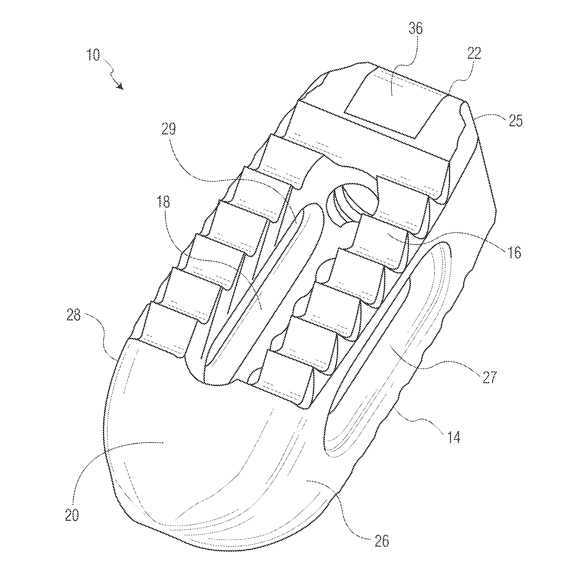
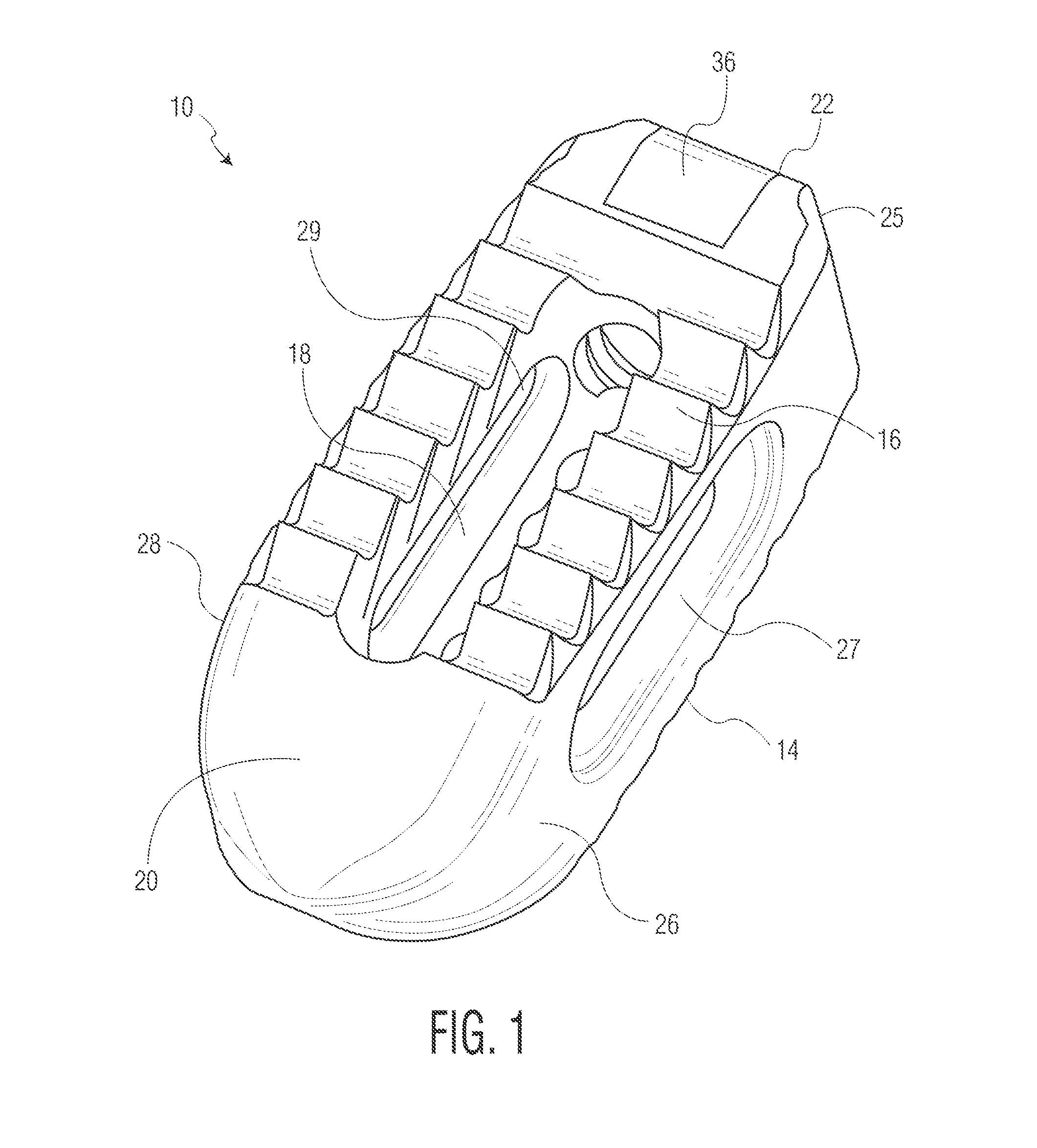
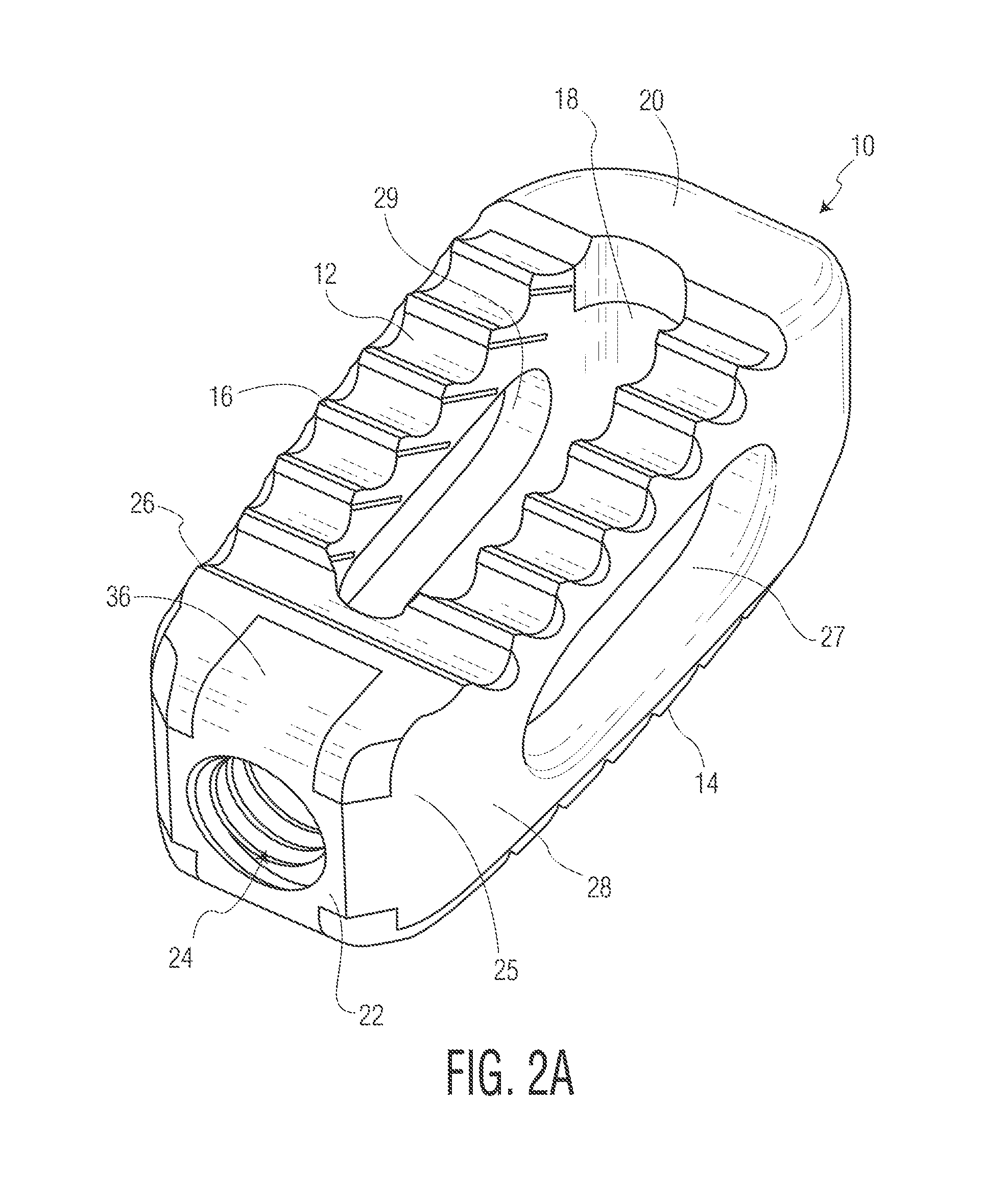
[0026]An implant 10 according to a first embodiment of the present invention is depicted in FIGS. 1-10 Implant 10 is shown as an implant suitable for implantation from a posterior approach. However, as will be readily apparent from the below discussion pertaining to other embodiments, the present invention is not limited to any particular type of implant design. Rather, it is contemplated that certain features of the present invention can be implemented in different types of implants. For instance, implants according to the present invention can be adapted for implantation from anterior or lateral aspects of the patient, as will be discussed below. Moreover, although disclosed as being constructed of metallic materials, it is contemplated that implants according to the present invention may be constructed of polymeric materials such as PEEK or the like. Additionally, each of the embodiments shown in the drawings are designed for placement between adjacent vertebral bodies. However, ...


PUM

PropertyMeasurementUnit
porosityaaaaaaaaaa
porosityaaaaaaaaaa
pore diameteraaaaaaaaaa

Abstract

A spinal implant including porous and solid portions is disclosed. The implant includes porous portions on upper and lower surfaces and in an interior thereof. Methods of manufacturing and implanting such implants are also disclosed.

Description

CROSS-REFERENCE TO RELATED APPLICATION[0001]The present application claims the benefit of the filing date of U.S. Provisional Patent Application No. 62 / 103,276, filed Jan. 14, 2015, the disclosure of which is hereby incorporated herein by reference.BACKGROUND OF THE INVENTION[0002]The present invention relates to spinal surgery, namely, implants utilized in fusing adjacent intervertebral bodies or the replacement of a vertebral body.[0003]Back pain can be caused by many different maladies, not the least of which are problems that directly impact the intervertebral discs of the spine. Typical disc issues include, inter alia, degeneration, bulging, herniation, thinning and abnormal movement. One method of treatment of such disc problems that has been widely utilized in the field of spinal surgery is a spinal fusion procedure, whereby an affected disc is removed, and the adjacent vertebral bodies are fused together through the use of interbody spacers, implants or the like. In some ins...

Claims


Application Information

Patent Timeline
Patent Type & Authority Applications(United States)
IPC IPC(8): A61F2/44A61F2/30
CPCA61F2/447A61F2/3094A61F2002/3092A61F2002/30904A61F2002/3093A61F2002/4475A61F2/44A61F2/4455A61F2/4611A61F2002/30985A61F2002/30011A61F2002/30593A61F2002/30772A61F2002/30784A61F2002/30962B33Y80/00B22F2005/005B22F5/10B22F7/002B22F7/08B22F3/24B22F2003/247B33Y10/00C22C1/0458Y02P10/25B22F10/20
Inventor WILLIS, STEVENZIELINSKA, JUSTYNA
Owner STRYKER EURO OPERATIONS HLDG LLC
Why Eureka
Try Eureka