Ink jet printing system and ink jet printing method

Inactive Publication Date: 2009-01-15
CANON KK
View PDF16 Cites 23 Cited by
  • Summary
  • Abstract
  • Description
  • Claims
  • Application Information

AI Technical Summary

Benefits of technology

[0016]The present invention has been accomplished with a view to overcoming the above-mentioned problems. It is therefore an object of this invention to provide an ink jet printing apparatus and a printing method that can produce high-quality images with no density unevenness betw

Problems solved by technology

Since an elongate print head is constructed of a large number of ink droplet ejection printing elements arranged in line at high density, it is extremely difficult to ensure that not a single printing element will result in an ejection failure, unavoidably leading to a reduced yield in a manufacturing process.
Such a “joining head” has a problem that when a plurality of printing element substrates, each having a plurality of ejection ports arrayed therein at a predetermined pitch, are put in place, it is unavoidable that some placement errors occur among the substrates.
Such substrate placement errors translate into inclinations among individual printing element substrates and variations in distance between the printing element substrates and a print medium, causing image impairments, such as black stripes and white stripes, to appear at merged portions of images formed by different scans.
With this arrangement, arrays of dots printed by the ejection ports of the overlapping portions D of two substrate are interpolated by those dots ejected from two kinds of ejection ports of other substrates, thereby distributing dot position errors, that are likely to concentrate on the jointing portion, over the entire overlapping portion.
In addition to the black or white stripes caused by the placement errors of the plurality of printi

Method used


Image

  • Ink jet printing system and ink jet printing method
  • Ink jet printing system and ink jet printing method
  • Ink jet printing system and ink jet printing method

Examples


first embodiment

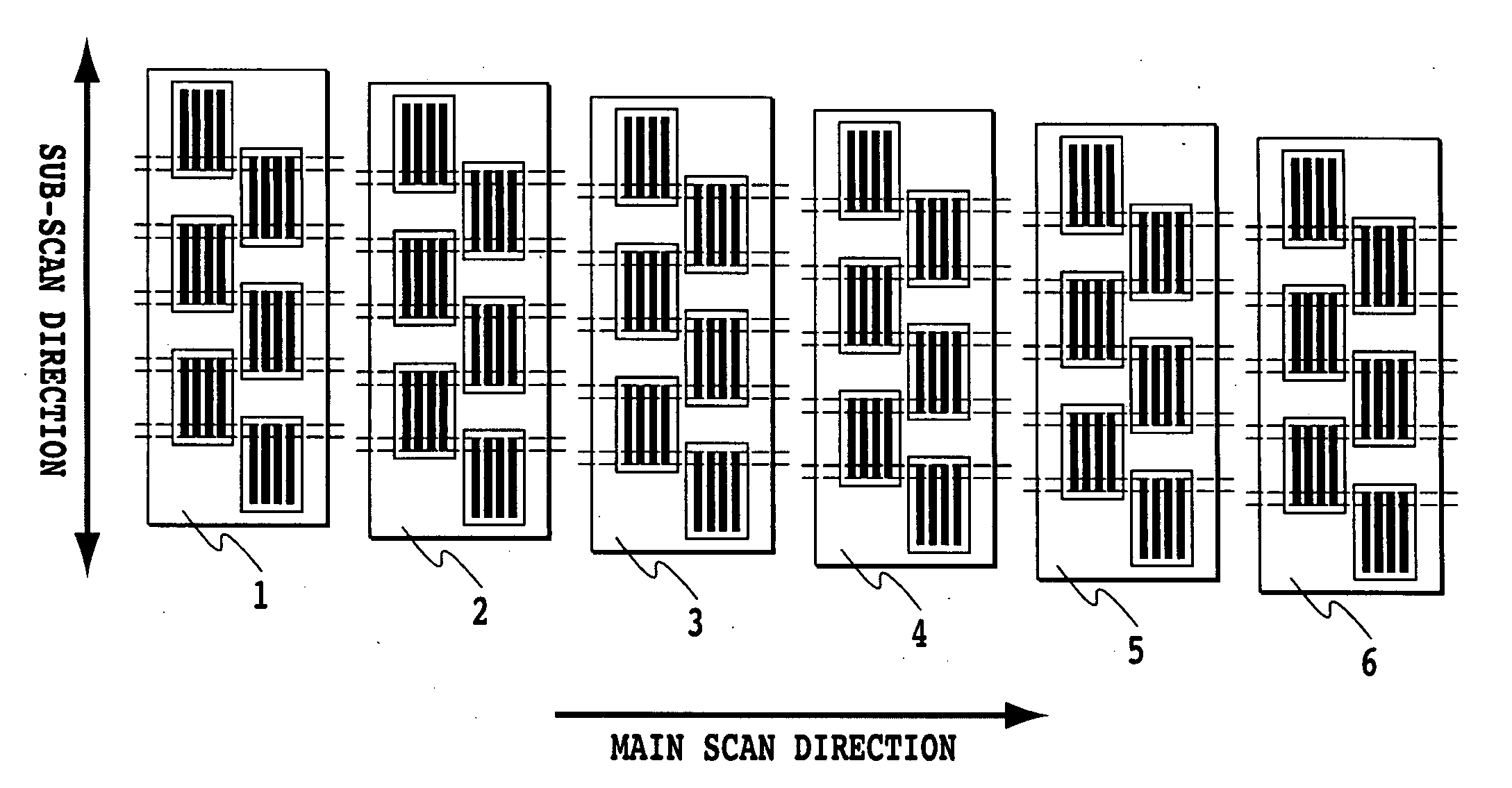
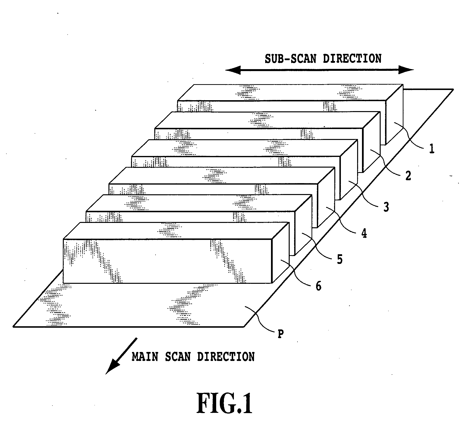
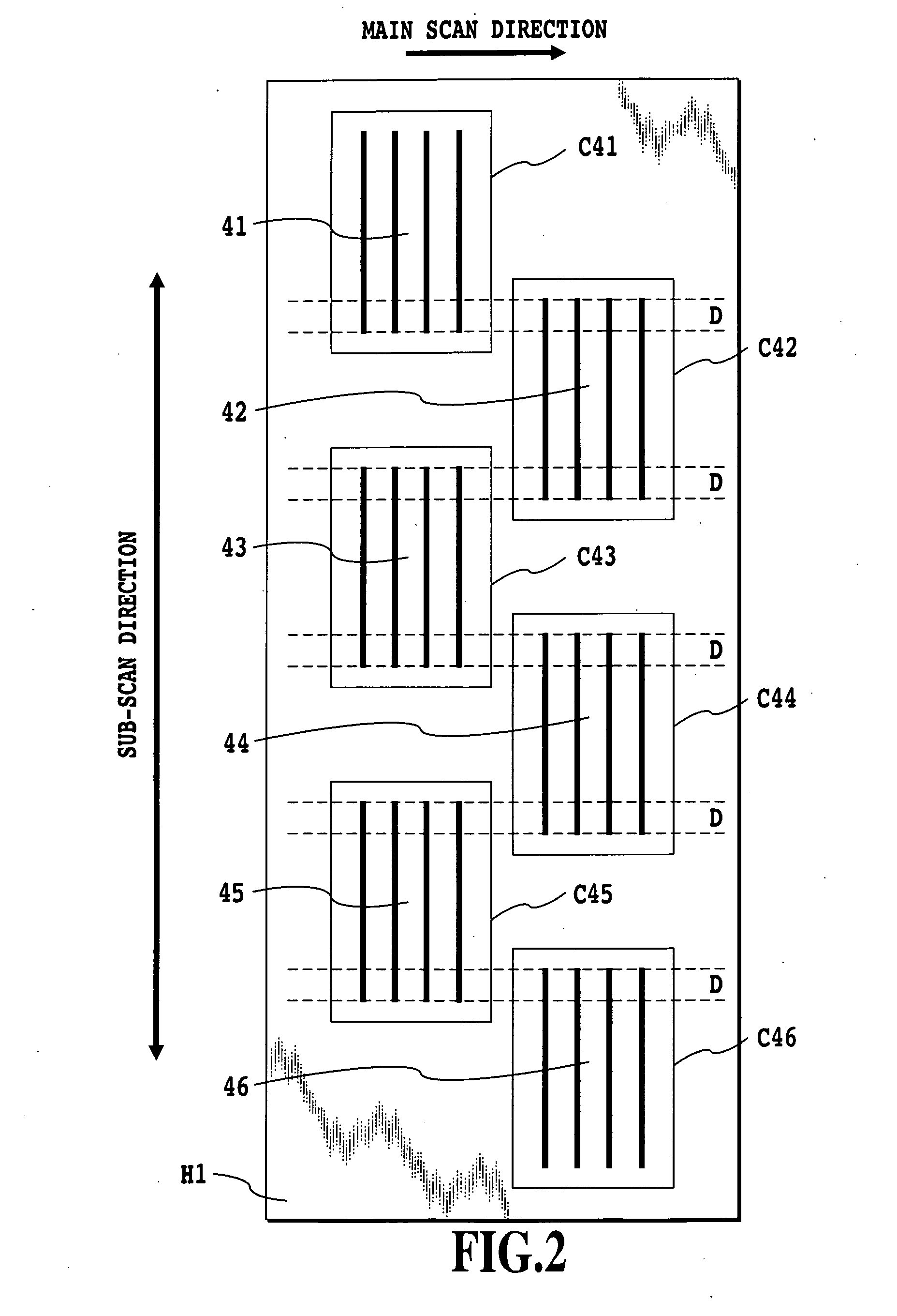
[0037]FIG. 1 is a schematic diagram showing a conceptual construction of an ink jet printing apparatus according to this embodiment. Elongate “joining heads”1-6 eject black (K), cyan (C), magenta (M), yellow (Y), light cyan (LC) and light magenta (LM) ink and constitute a head unit fixedly installed in the printing apparatus. The “joining heads”1-6 are each connected with an ink supply tube not shown and with cables not shown for sending and receiving control and other signals. A print medium P, such as plain paper, high-quality dedicated paper, OHP sheet, glossy paper, glossy film and post card, is held between conveying rollers or paper discharge rollers not shown and conveyed at a constant speed in a main scan direction as a conveying motor driving. A number of printing elements, arranged in a sub-scan direction, of the “joining heads”1-6 eject ink at a predetermined frequency in synchronism with a timing at which a linear encoder (not shown) reads the position of the print mediu...

second embodiment

[0066]While the first embodiment has been shown to be effective in the full line type printing apparatus, this invention can also be applied to a serial type printing apparatus that does not use “joining heads”.

[0067]FIG. 11 is a schematic view showing a print head of this embodiment that can be mounted in a serial type printing apparatus. The print heads 11-16 have the same construction and are arranged slightly staggered in the sub-scan direction. With this arrangement of the print heads 11-16 that eject different color inks, seam stripes between individual printing scans are formed at different positions for different ink colors. The print heads 11-16 are integrally constructed in a positional relation shown in the figure to form a print head cartridge 1100.

[0068]FIG. 12 is a schematic diagram showing how the print head cartridge 1100 is scanned over a print medium for printing. The serial type printing apparatus forms an image on a print medium by repeating the printing scan in ...


PUM


Abstract

An image data signal value conversion is performed such that the volume of ink applied to image areas on a print medium to be printed by the overlapping portions of the printing element substrates is smaller than that applied to image areas on the print medium to be printed by other than the overlapping portions. Alternatively, the image data signal value conversion is performed such that the volume of ink applied to overlapping areas on the print medium to be printed by two consecutive printing main scans is smaller than that applied to other than the overlapping areas. For this reason, even when forming photographic images by using an elongate “joining head”, high-quality images with no density unevenness between overlapping areas and other areas on a print medium can be produced. Also in a serial type printing apparatus, uniform images with no seam stripes can be produced.

Description

BACKGROUND OF THE INVENTION[0001]1. Field of the Invention[0002]The present invention relates to an ink jet printing apparatus that prints images by using an elongate print head comprising a plurality of printing element substrates, each having arrays of a plurality of ink ejection printing elements. More particularly it relates to a printing method to prevent seam stripes and density unevenness caused by print areas of the plurality of printing element substrates overlapping one another. It also relates to a printing method to prevent seam stripes and density unevenness that would otherwise occur at boundaries between print areas of a plurality of print scans.[0003]2. Description of the Related Art[0004]Ink jet printing apparatus in general are classified largely into two types—serial type and full line type. The serial type ink jet printing apparatus forms an image by repetitively alternating a printing main scan that moves the print head in a main scan direction while ejecting in...

Claims


Application Information

Patent Timeline
IPC IPC(8): B41J29/38
CPCB41J2/2146B41J2/155B41J29/38
Inventor OCHIAI, TAKASHITSUBOI, HITOSHIWADA, SATOSHI
Owner CANON KK
Why Eureka
Try Eureka