Imaging lens and imaging apparatus

a technology of imaging apparatus and lens, applied in the direction of optics, instruments, optics, etc., can solve the problems of difficult implementation of further compactness, affecting the performance of the lens, and affecting the effect of balancing

Inactive Publication Date: 2007-04-17
SONY CORP
View PDF6 Cites 8 Cited by
  • Summary
  • Abstract
  • Description
  • Claims
  • Application Information

AI Technical Summary

Benefits of technology

[0021]According to the above, an imaging apparatus can be obtained that is very compact and has high optical performance suitable while the imaging lens is configured of a few number of lenses or as few as two lenses. In addition, with the imaging lens being used, a high-pixel density imaging device is used, thereby enabling high quality images to be obtained and enabling an imaging apparatus to be compactly configured.
[0022]In addition, the imaging lens according to the embodiment of the invention achieves the compactness, and concurrently, has a high lens performance with appropriately corrected aberrations of the total lens length. Further, since the aperture diaphragm is positioned between the first and second lenses, sensitivity is low for imperfect axial alignment between the first and second lenses, aligned assembly requiring an expensive, machine and time is not necessary, thereby enhancing mass-productivity. Further, with the imaging lens being used, a high-pixel density imaging device is used, thereby to enable high quality images to be obtained and to enable an imaging apparatus to be configured compactly.
[0023]Other embodiments of the imaging lens and imaging apparatus of the invention each satisfy (4) 0.05≦d1 / f≦0.09 and (5) 0.10≦d2 / f≦0.18, where f represents the focal distance of the total lens system, d1 represents a distance from a surface on the image side of the first lens to the aperture diaphragm, and d2 represents a distance from the aperture diaphragm to a surface on the object side of the second lens. Accordingly, further sufficient correction of aberrations becomes possible. In addition, the aperture diaphragm can be disposed in a desired position.
[0025]According to still other embodiments of the imaging lens and imaging apparatus of the invention, the surface on the object side of the first lens satisfies a conditional expression (6) 55°<|θ1(h)|<80°, where θ1(h) represents a tilt of the surface on the object side of the first lens at a height h(=D1 / 2), D1 representing an effective diameter of the surface on the object side of the first lens. Accordingly, off-axis aberrations can be corrected with good balancing.
[0026]According to yet other embodiments of the imaging lens and imaging apparatus of the invention, the surface on the image side of the second lens satisfies a conditional expression (7) 55°<|θ2(h)|<80°, where θ2(h) represents a tilt of the surface on the image side of the second lens at the height h(=D2 / 2), D2 representing an effective diameter of the surface on the image side of the second lens. Accordingly, off-axis aberrations can be corrected with good balancing.

Problems solved by technology

In the case of the imaging lens disclosed in Japanese Unexamined Patent Application Publication No. 2003-215446, however, while doublet configuration and compactness are implemented, various types of substantial aberrations take place.
In this case, the requirement for lens performance suitable to the high-pixel density imaging device cannot be satisfied.
In this case, physical constraints take place, thereby making it difficult to implement further compactness.

Method used


Image

  • Imaging lens and imaging apparatus
  • Imaging lens and imaging apparatus
  • Imaging lens and imaging apparatus

Examples


first embodiment

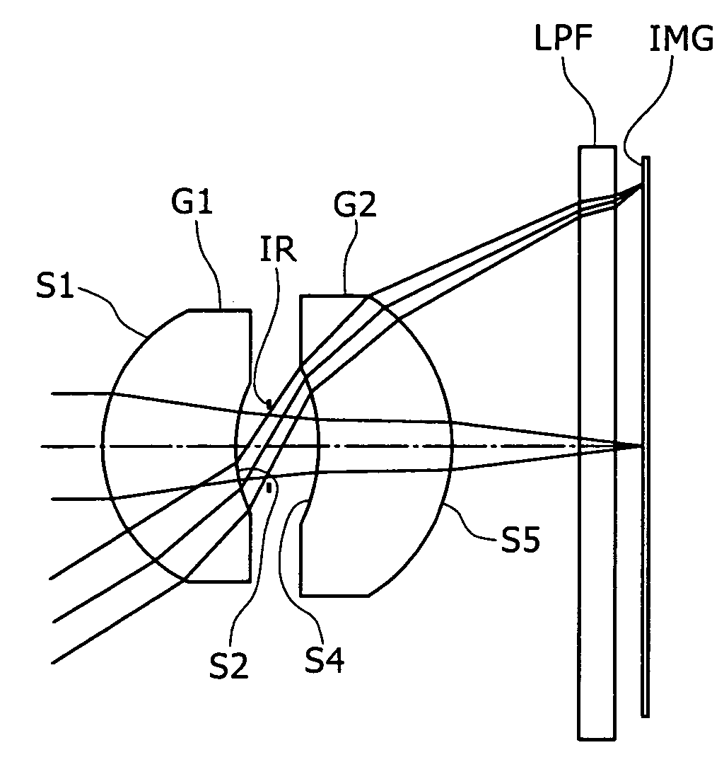
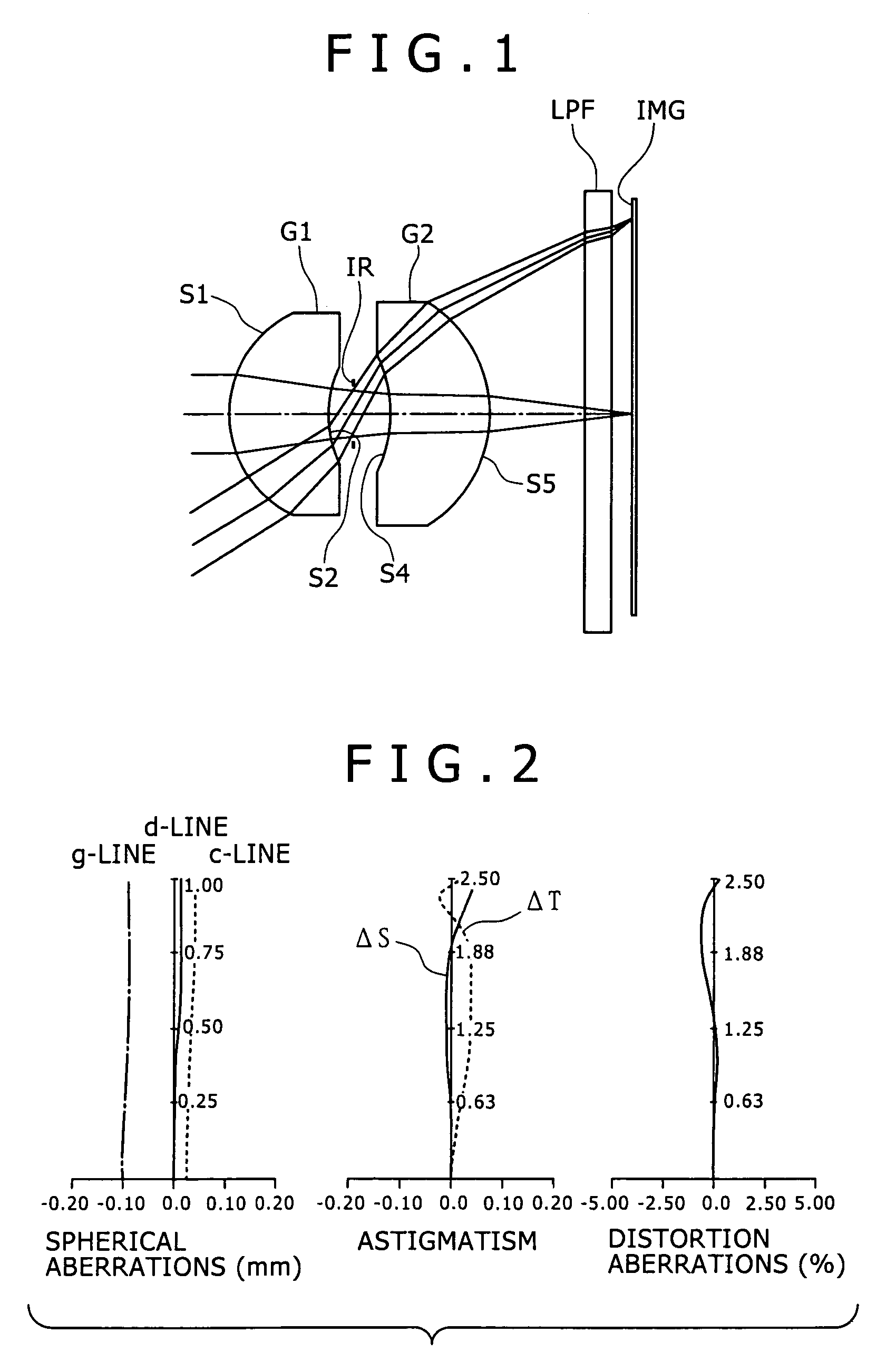
[0081]FIG. 1 is a view showing a lens configuration according to a first embodiment of the present invention. An imaging lens of the first embodiment is configured of a first lens G1, a second lens G2, and an aperture diaphragm IR that are arrayed in that order from the object side. The first lens G1 has a meniscus profile with a convex surface facing the object side and has a positive refractive index, and the second lens G2 has a meniscus profile with a convex surface facing the image side and has a positive refractive index. An “LPF” is a lowpass filter interposed between the second lens G2 and an imaging plane IMG.

[0082]Table 1 shows data of an optical system according to a numeric embodiment 1 in the case where practical numeric values are applied to the first embodiment.

[0083]

TABLE 1FNo = 4.0f = 4.092ω = 62.72°SiRidiniυi1  1.529 (ASP)1.251.768049.22  1.648 (ASP)0.303Aperture0.484−3.242 (ASP)1.281.814737.05−2.130 (ASP)1.266∞0.301.516864.27∞0.308IMG

[0084]In the first embodiment,...

second embodiment

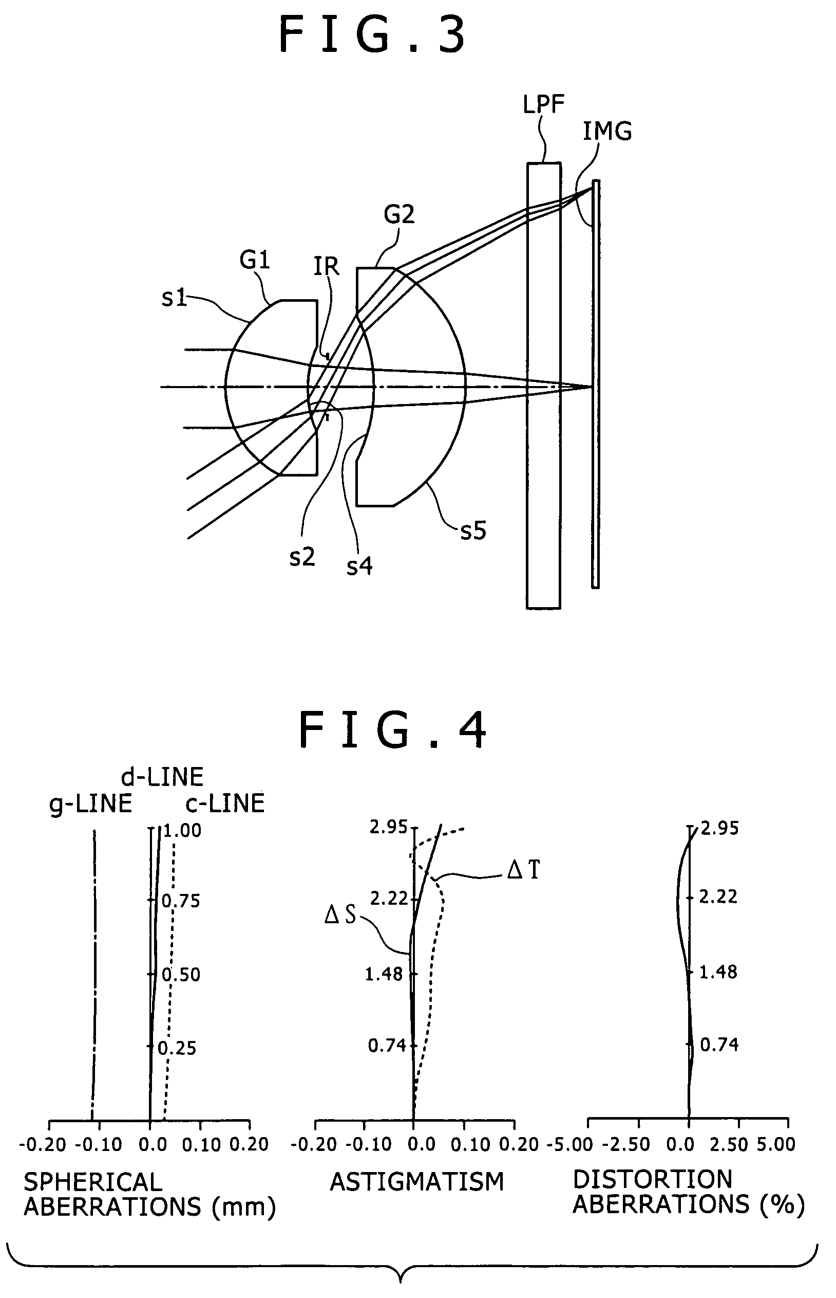
[0088]FIG. 3 is a view of a lens configuration according to a second embodiment of the present invention. An imaging lens of the second embodiment is configured of a first lens G1, a second lens G2, and an aperture diaphragm IR that are arrayed in that order from the object side. The first lens G1 has a meniscus profile with a convex surface facing the object side and has a positive refractive index, and the second lens G2 has a meniscus profile with a convex surface facing the image side and has a positive refractive index. An “LPF” is a lowpass filter interposed between the second lens G2 and an imaging plane IMG.

[0089]Table 3 shows data of an optical system according to a numeric embodiment 2 in the case where practical numeric values are applied to the second embodiment.

[0090]

TABLE 3FNo = 4.0f = 4.612ω = 65.03°SiRidiniυi1  1.444 (ASP)1.211.743349.32  1.460 (ASP)0.303Aperture0.704−4.035 (ASP)1.381.814737.05−2.572 (ASP)0.936∞0.501.516864.27∞0.508IMG

[0091]In the second embodiment, ...

third embodiment

[0095]FIG. 5 is a view of a lens configuration according to a third embodiment of the present invention. An imaging lens of the third embodiment is configured of a first lens G1, a second lens G2, and an aperture diaphragm IR that are arrayed in that order from the object side. The first lens G1 has a meniscus profile with a convex surface facing the object side and has a positive refractive index, and the second lens G2 has a meniscus profile with a convex surface facing the image side and has a positive refractive index. An “LPF” is a lowpass filter interposed between the second lens G2 and an imaging plane IMG.

[0096]Table 5 shows data of an optical system according to a numeric embodiment 3 in the case where practical numeric values are applied to the third embodiment.

[0097]

TABLE 5FNo = 4.0f = 3.542ω = 62.69°SiRidiniυi1  1.389 (ASP)1.061.743349.32  1.507 (ASP)0.263Aperture0.404−2.353 (ASP)1.071.806140.75−1.611 (ASP)1.386∞0.301.516864.27∞0.308IMG

[0098]In the third embodiment, both...


PUM


Abstract

An imaging lens system includes a first lens having a meniscus profile with a convex surface facing an object side and having a positive refractive index; an aperture diaphragm; and a second lens having a meniscus profile with a convex surface facing an image side and having a positive refractive index, wherein the first lens, the aperture diaphragm, and the second lens are arranged in this order from the object side. The imaging lens satisfies conditional expressions where f represents a focal distance of a total lens system, f1 represents a focal distance of the first lens, and L represents a distance on the optical axis from the surface on the object side of the first lens to an image plane wherein calculation is done in terms of an air-equivalent thickness for a back insertion glass, and n(ave) represents an average value of refractive indexes at d-lines of the first and second lenses.

Description

[0001]The present invention contains subject matter related to Japanese Patent Application JP 2004-246829 filed in the Japanese Patent Office on Aug. 26, 2004, the entire contents of which being incorporated herein by reference.BACKGROUND OF THE INVENTION[0002]1. Field of the Invention[0003]The present invention relates to imaging lenses and imaging apparatuses. More specifically, the invention relates to an imaging lens suited for use in compact imaging apparatuses using a solid state imaging device, such as a charge coupled device (CCD) or complementary metal-oxide semiconductor (CMOS) and to an imaging apparatus using the lens.[0004]2. Description of the Related Art[0005]As apparatuses using a solid state imaging device, such as a CCD or CMOS, camera-enabled mobile phones, digital still cameras, and such other apparatuses are known. In the field of such imaging apparatuses, further size reduction or compactness is demanded, so that an imaging lens being mounted therein is require...

Claims


Application Information

Patent Timeline
Patent Type & Authority Patents(United States)
IPC IPC(8): G02B9/04G02B9/08
CPCG02B13/003G02B13/18
Inventor TAMURA, MASAKI
Owner SONY CORP
Why Eureka
Try Eureka