Image sensing apparatus and method for accurate dark current recovery of an image signal

Inactive Publication Date: 2009-11-24
CANON KK
View PDF13 Cites 8 Cited by
  • Summary
  • Abstract
  • Description
  • Claims
  • Application Information

AI Technical Summary

Benefits of technology

[0011]The present invention has been made in consideration of the conventional situation, and has as its object to provide an image sensing apparatus capable of recoverin

Problems solved by technology

The clamping circuit 103 executes erroneous DC recovery operati

Method used


Image

  • Image sensing apparatus and method for accurate dark current recovery of an image signal
  • Image sensing apparatus and method for accurate dark current recovery of an image signal
  • Image sensing apparatus and method for accurate dark current recovery of an image signal

Examples


first embodiment

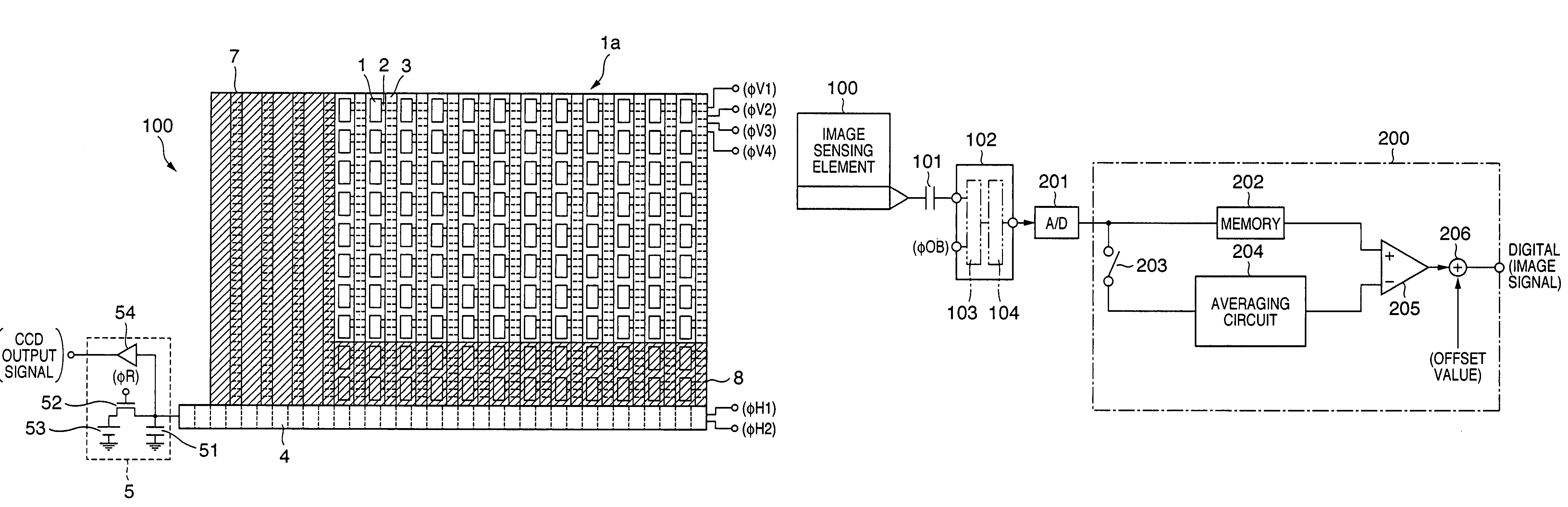
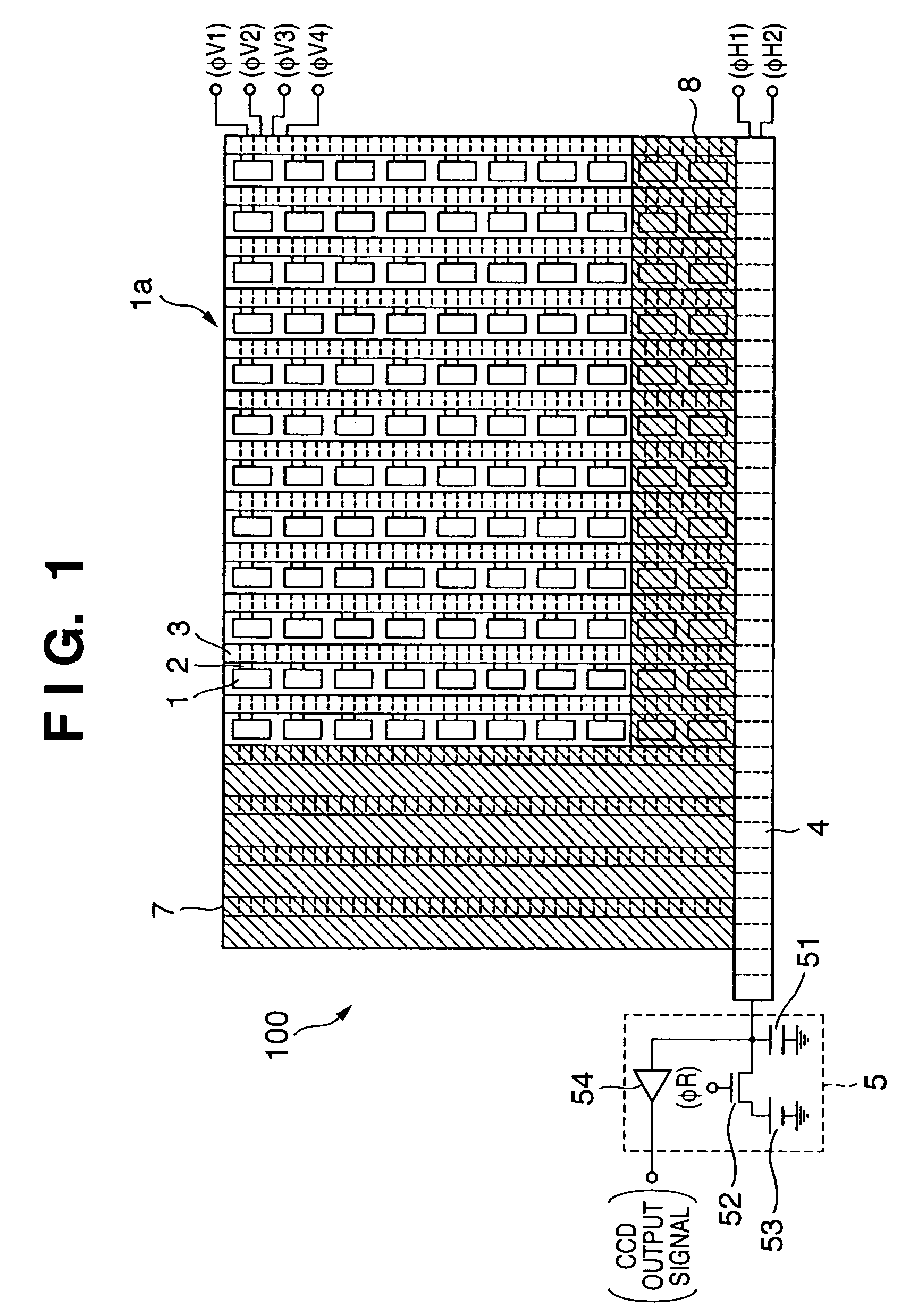
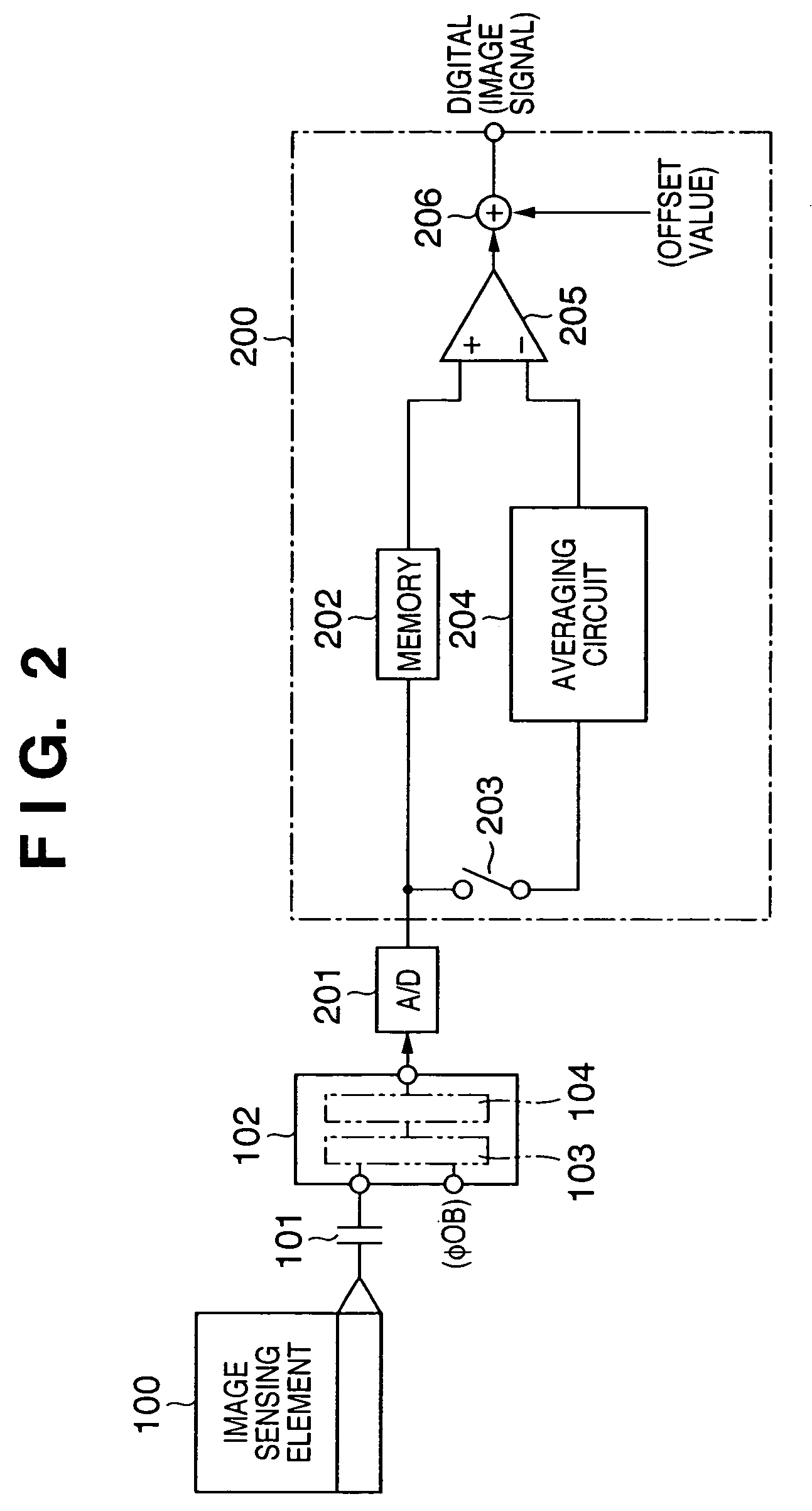
[0024]FIGS. 1 and 2 are views for explaining an image sensing apparatus according to the first embodiment of the present invention. The image sensing apparatus according to the first embodiment includes an image sensing element 100 which is formed by an interline CCD, as shown in FIG. 1, an analog signal processing circuit 102 which is AC-coupled to the CCD output side of the image sensing element 100 via a capacitor 101, as shown in FIG. 2, and performs signal processing including clamping on the first stage (to be referred to as “first clamping” hereinafter) out of two-stage clamping of recovering a DC component from a CCD output signal output from the image sensing element 100, and a digital signal processing circuit which is connected to the analog signal processing circuit 102 via an A / D converter 201 and performs signal processing including clamping on the second stage (to be referred to as “second clamping” hereinafter) for the digital signal of an image signal having undergo...

second embodiment

[0037]FIG. 3 shows the arrangement of a DC recovery circuit in an image sensing apparatus according to the second embodiment of the present invention. In the second embodiment, an image sensing element 100 and first clamping circuit 103 are identical to those in the first embodiment, a description thereof will be omitted, and only the difference will be explained. In the second embodiment, the lowest value among average values obtained by dividing a vertical optical black region 8 into a plurality of regions and calculating the average value of signals from the vertical optical black region 8 for each divided region is used as the average value of signals from the vertical optical black region 8 that is to be subtracted from an image signal stored in a memory 202 in a second clamping circuit 200 serving as a second correction device for the second DC recovery.

[0038]As this circuit arrangement, the image sensing apparatus shown in FIG. 3 comprises a plurality of (three in this exampl...


PUM


Abstract

An object of this invention is to enable performing accurate DC recovery operation for an output signal from an image sensing element, and obtaining a high-quality image free from any image degradation such as a horizontal streak. To achieve this object, an image sensing apparatus includes first and second clamping circuits on the output side of an image sensing element. The image sensing element outputs a signal from an effective pixel region, a first reference signal for DC recovery of an image signal that is set for each row, and a second reference signal that is uniformly set for the pixel region. The first clamping circuit DC-recovers a signal from the effective pixel region for each row on the basis of the first reference signal. The second clamping circuit uniformly DC-recovers signals from the effective pixel region for the pixel region on the basis of the second reference signal. The first reference signal is a signal obtained in a horizontal reference region free from any influence of an output from the photodiode of the image sensing element. The second reference signal is a signal which is obtained in a vertical optical black region and contains a dark current component generated in the photodiode of the image sensing element.

Description

FIELD OF THE INVENTION[0001]The present invention relates to an image sensing apparatus and, more particularly, to DC recovery operation of an image sensing apparatus in which an image signal output from an image sensing element contains a signal from an effective pixel region and a signal from a DC recovery reference region.BACKGROUND OF THE INVENTION[0002]Image sensing elements used in an electronic still camera and the like are mainly interline CCDs (Charge-Coupled Devices). A conventional image sensing apparatus using the interline CCD is illustrated in FIGS. 7 and 8.[0003]The conventional image sensing apparatus shown in FIGS. 7 and 8 includes an image sensing element 100 which is formed by an interline CCD, and an analog signal processing circuit 102 which is connected (AC-coupled) to the signal output side of the image sensing element 100 via a capacitor 101.[0004]As shown in FIG. 7, the image sensing element 100 is comprised of a plurality of photodiodes 1 serving as photoel...

Claims


Application Information

Patent Timeline
IPC IPC(8): H04N5/16H04N5/335H04N5/361H04N5/369H04N5/3728H04N5/378
CPCH04N5/361H04N25/63
Inventor TAKEDA, NOBUHIRO
Owner CANON KK
Why Eureka
Try Eureka