Check patentability & draft patents in minutes with Patsnap Eureka AI!

Method, apparatus, system, and computer program to debug an optical network terminal using diagnostic optical network terminal

Inactive Publication Date: 2009-01-15
TELLABS VIENNA
View PDF5 Cites 24 Cited by
  • Summary
  • Abstract
  • Description
  • Claims
  • Application Information

AI Technical Summary

Problems solved by technology

While users sometimes may be able to solve problems on their own without any assistance from the service provider, very often the users cannot do so, and thus they seek troubleshooting assistance from a service provider's customer service entity and/or field technicians.
As can be appreciated, such assistance can be costly and inefficient to the service provider, particularly when truck-rolls are involved.
Moreover, even in cases where a technician assists in troubleshooting a problem on-site, the technician may not be able to recognize the source of the problem and still may have to contact a network operations center in an attempt to do so.
As with most electronic equipment, an ONT can malfunction.
In some cases ONT malfunctions are catastrophic to communications.
This can make it impossible for the OLT to communicate with any of the ONTs on the ODN.
Also, in some cases an ONT emits signals that it is eventually going to fail.
In addition, once an ONT is ranged, the presence of an error might be undetectable until ranging reoccurs.
Thus, only when the ranging process needs to reoccur will such a range blocking type error be detected.
This results in the OLT not being able to communicate with any of the ONTs on the ODN.
An ONT has many failure modes that result in service problems.
Because an ONT malfunction may cause problems upstream and downstream of itself, service problems may be caused for one or more customers, thereby making troubleshooting more difficult.
For example, a malfunctioni

Method used


Image

  • Method, apparatus, system, and computer program to debug an optical network terminal using diagnostic optical network terminal
  • Method, apparatus, system, and computer program to debug an optical network terminal using diagnostic optical network terminal
  • Method, apparatus, system, and computer program to debug an optical network terminal using diagnostic optical network terminal

Examples


Example

[0036]Reference numerals that are the same but which appear in different figures represent the same elements, even if those elements are not described with respect to each figure.

DETAILED DESCRIPTION OF THE INVENTION

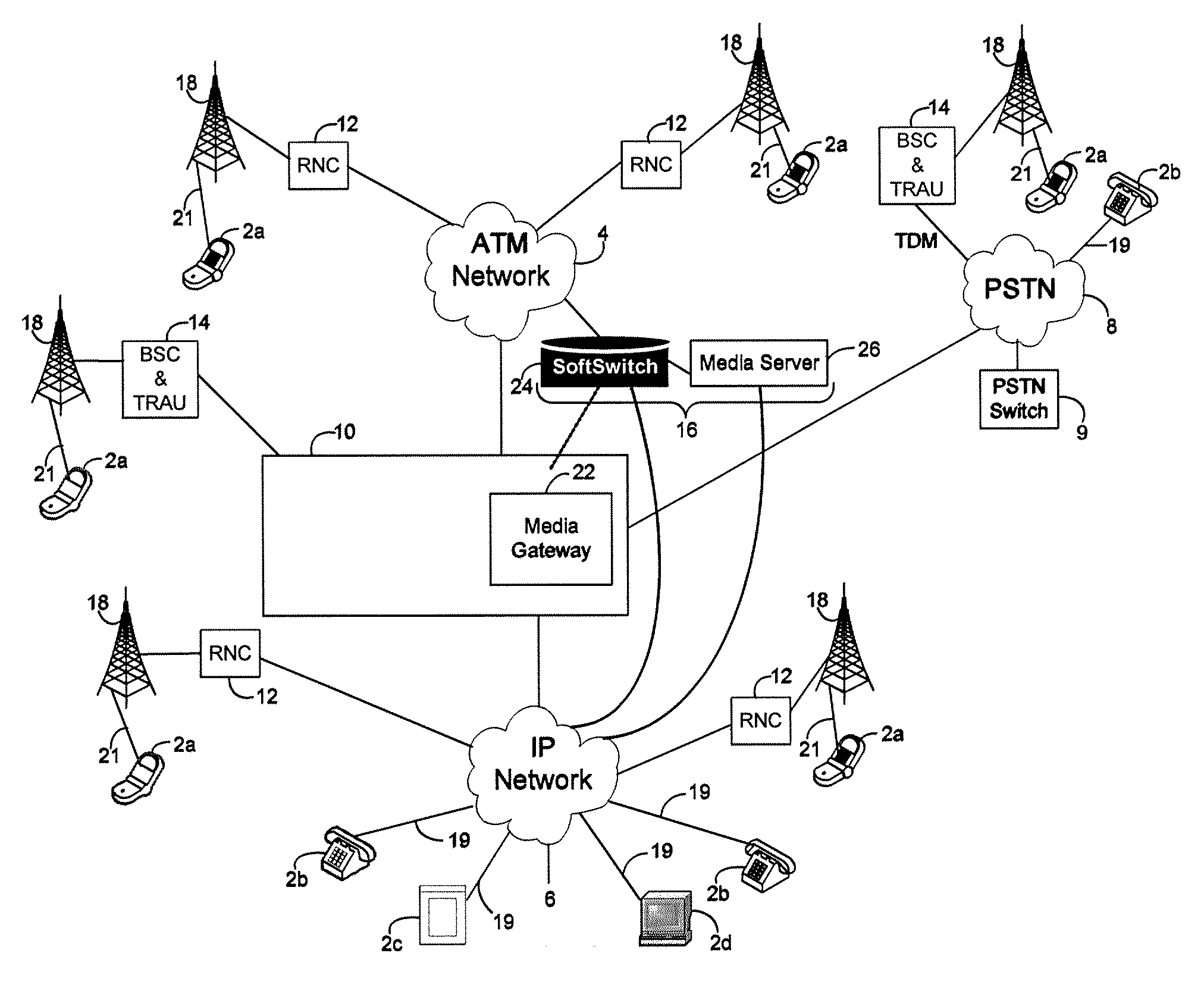
[0037]FIG. 2 is a block diagram of a communication system 1 that is suitable for practicing this invention. In the illustrated embodiment, the communication system 1 comprises customer premises equipment such as user communication terminals (devices) 2a, 2b, video devices 2c, computer terminals 2d, and also comprises a plurality of communication networks 4, 6, 8, a gateway 10, and various communication and / or control stations such as, for example, Radio Network Controllers (RNCs) 12, Base station Controllers (BSCs) and Transcoder Rate Adaptor Units (TRAUs), the latter two of which are shown and referred to hereinafter collectively as BSCs / TRAUs 14, base sites or base stations 18, and an Integrated Multimedia Server (IMS) 16. Conventionally, various types of interconnecti...


PUM


Abstract

A method of detecting a problem in a communication network that supports at least one communication service communication service is provided. The method includes disconnecting a suspect component from the network, and replacing the suspect component with a diagnostic component configured to have the same network identification information as the suspect component. The method also includes determining if the problem still exists, and identifying the suspect component as defective if the problem no longer exists. In addition, the method includes identifying the problem as being caused by another part of the network besides the suspect component, if the problem still exists. An apparatus, system, and computer program are also provided for carrying out the method.

Description

BACKGROUND OF THE INVENTION[0001]1. Field of the Invention[0002]The present invention relates generally to diagnostics and troubleshooting for optical network equipment, and, more particularly, to diagnostic methods, systems, equipment, and computer programs usable by technicians for identifying defective optical network terminals (ONT) within a passive optical network (PON).[0003]2. Description of the Related Art[0004]There is a growing demand in the industry to find a solution to transmit voice, data, or video from a headend to a subscriber's premises through a fiber optic network all the way into an individual home or business. Such fiber optic networks generally are referred to as fiber-to-the-home (FTTH), fiber-to-the-premises (FTTP), fiber-to-the-business (FTTB), fiber-to-the-node (FTTN), or fiber-to-the-curb (FTTC) networks and the like, depending on the specific application of interest. Such types of networks are also referred to herein generally as “FTTx networks”.[0005]In ...

Claims


Application Information

Patent Timeline
IPC IPC(8): H04B10/08
CPCH04L12/2697H04L41/0631H04Q2011/0081H04Q11/0067H04L43/50
Inventor LIU, DAVID H.MERRITT, GUY M.MANNIX, BRENDAN
Owner TELLABS VIENNA
Features
  • R&D
  • Intellectual Property
  • Life Sciences
  • Materials
  • Tech Scout
  • Unparalleled Data Quality
  • Higher Quality Content
  • 60% Fewer Hallucinations
Learn More