Method and apparatus for identifying faults in a passive optical network

a passive optical network and fault identification technology, applied in the direction of electrical equipment, transmission monitoring, transmission monitoring/testing/fault measurement system, etc., can solve problems such as bursty, rogue ont condition, and failure to identify faults

Inactive Publication Date: 2009-01-08
TELLABS PETALUMA
View PDF11 Cites 43 Cited by
  • Summary
  • Abstract
  • Description
  • Claims
  • Application Information

AI Technical Summary

Problems solved by technology

This can make it difficult for the receiver of that signal, either the ONT or OLT, to communicate consistently and may result in misinterpreted commands that disrupt other ONT's communications, resulting in a rogue ONT condition.
Existing error detection techniques, such as those described in the various PON protocols, may not detect SNR types of faults or if detected (e.g., by system failure), they may not be identified as faults due to low SNR.
These bursty, intermittent types of errors may not occur long enough to generate the G.983.1 standard SDi, LCD, OAML or FRML type error conditions.
However, these faulty communications can lead to incorrect OLT

Method used


Image

  • Method and apparatus for identifying faults in a passive optical network
  • Method and apparatus for identifying faults in a passive optical network
  • Method and apparatus for identifying faults in a passive optical network

Examples


Embodiment Construction

[0014]A description of example embodiments of the invention follows.

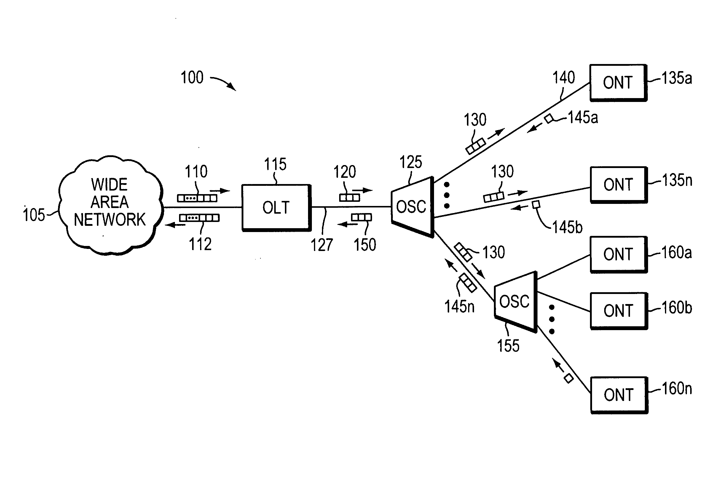
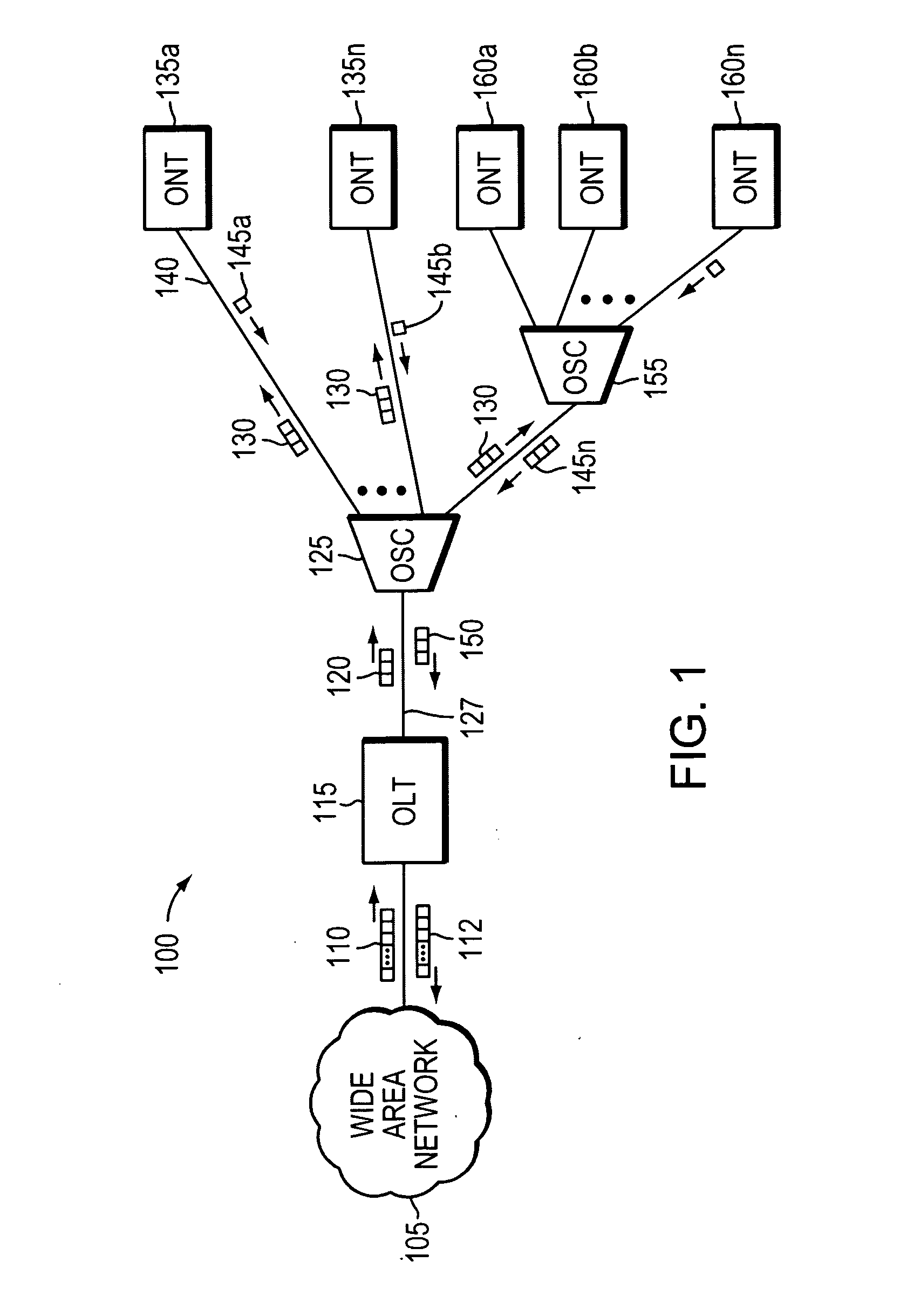
[0015]FIG. 1 is a network diagram of a passive optical network (PON) 100 illustrating aspects of an example embodiment of the invention. The PON 100 includes an optical line terminal (OLT) 115, an optical splitter / combiner (OSC) 125, and at least one optical network unit (ONT) 135a-n, 160a-n. In other network embodiments, optical network units (ONUs) (not shown) may be in optical communication with multiple ONT(s) 135a-n, 160a-n directly in electrical communication with end user equipment, such as routers, telephones, home security systems, and so forth (not shown). As presented herein, ONU's are typically found at a curb and ONT(s) extend to a premise, but both generally behave the same with respect to embodiments of this invention. Data communications 110 may be transmitted to the OLT 115 from a wide area network (WAN) 105. “Data” as used herein refers to voice, video, analog, or digital data.

[0016]Communication o...


PUM


Abstract

Component malfunctions in passive optical networks (PON) can increase bit error rates and decrease signal-to-noise ratio in communications signals. These faults may cause the receivers of the signals, either the optical line terminal (OLT) or optical network terminals (ONTs), to experience intermittent faults and/or may result in misinterpreted commands that disrupt other ONT's communication, resulting in a rogue ONT condition. Existing PON protocol detection methods may not detect these types of malfunctions. An embodiment of the present invention identifies faults in a PON by transmitting a test series of data patterns via an optical communications path from a first network node to a second network node. The test series is compared to an expected series of data patterns. An error rate may be calculated as a function of the differences between the test series and expected series. The error rate may be reported to identify faults in the PON.

Description

BACKGROUND OF THE INVENTION[0001]In a passive optical network (PON), multiple optical network terminals (ONTs) or optical network units (ONUs) transmit data to an optical line terminal (OLT) using a common optical wavelength and fiber optic media. Various components of the optical distribution network (ODN), including the OLT, optical components, and ONT(s), can malfunction in such a way that upstream and / or downstream communications signals have too low a signal-to-noise ratio (SNR). This can make it difficult for the receiver of that signal, either the ONT or OLT, to communicate consistently and may result in misinterpreted commands that disrupt other ONT's communications, resulting in a rogue ONT condition.[0002]Existing error detection techniques, such as those described in the various PON protocols, may not detect SNR types of faults or if detected (e.g., by system failure), they may not be identified as faults due to low SNR. For example, in certain situations, a faulty ONT ma...

Claims


Application Information

Patent Timeline
IPC IPC(8): H04B10/08
CPCH04B10/079H04B10/035
Inventor DELEW, DAVID A.GUPTA, VINITAEGBERTS, BERNARDUS F.SMITH, DANIEL L.HENDERSON, PAUL A.SACKMAN, EDWARD J.WURST, MICHAEL J.
Owner TELLABS PETALUMA
Why Eureka
Try Eureka