Optical network

a technology of optical networks and optical fibers, applied in the field of optical networks, can solve the problems of not being able to use such wavelengths in none-wdm systems, and achieve the effect of efficient us

Inactive Publication Date: 2011-06-30
TELEFON AB LM ERICSSON (PUBL)
View PDF7 Cites 44 Cited by
  • Summary
  • Abstract
  • Description
  • Claims
  • Application Information

AI Technical Summary

Benefits of technology

[0008]Such a network configuration goes against established principles, as the second PON OLT uses a wavelength within an amplification band of a doped fibre amplifier. Such wavelengths are normally restricted for use in WDM systems, and it is known that it is not desirable to use such wavelengths in none-WDM systems. However, the present inventors have realised that this counter-intuitive selection of wavelengths, in combination with the particular configuration described, allows a PON network such as a GPON to be upgraded in two steps, first to include the second PON OLT transmitting at a faster bit rate (e.g. at 10 Gb / s), and then subsequently upgraded to include a third PON OLT (which could use WDM). Thus the original network infrastructure of transmission fibre can be maintained, and efficiently used.

Problems solved by technology

Such wavelengths are normally restricted for use in WDM systems, and it is known that it is not desirable to use such wavelengths in none-WDM systems.

Method used


Image

  • Optical network
  • Optical network
  • Optical network

Examples


Embodiment Construction

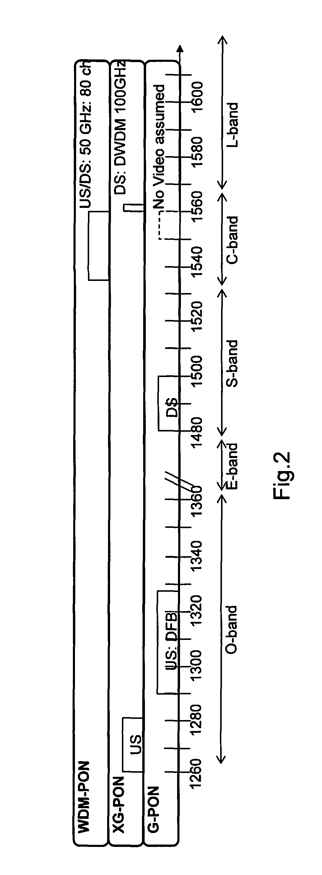
[0034]The present inventors has realised that whilst the next generation of fibre access networks may rely on WDM techniques, it can be desirable to upgrade existing fibre access networks such as PON with faster bit-rate systems. For example, an existing GPON could be upgraded by incorporating 10G PON (i.e. passive optical network technology configured to transmit at 10 Gb / s, four times the bit-rate of GPON systems).

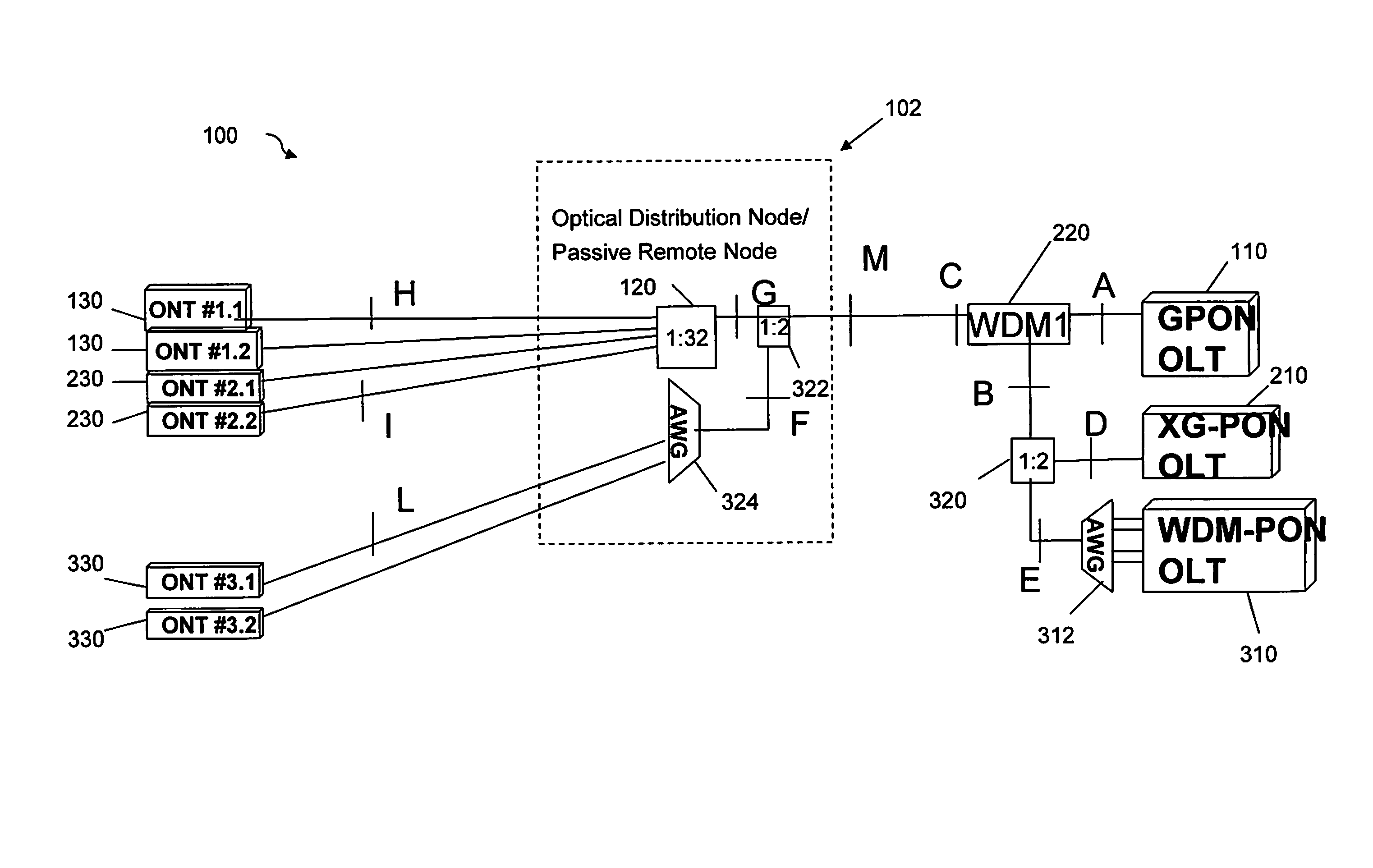
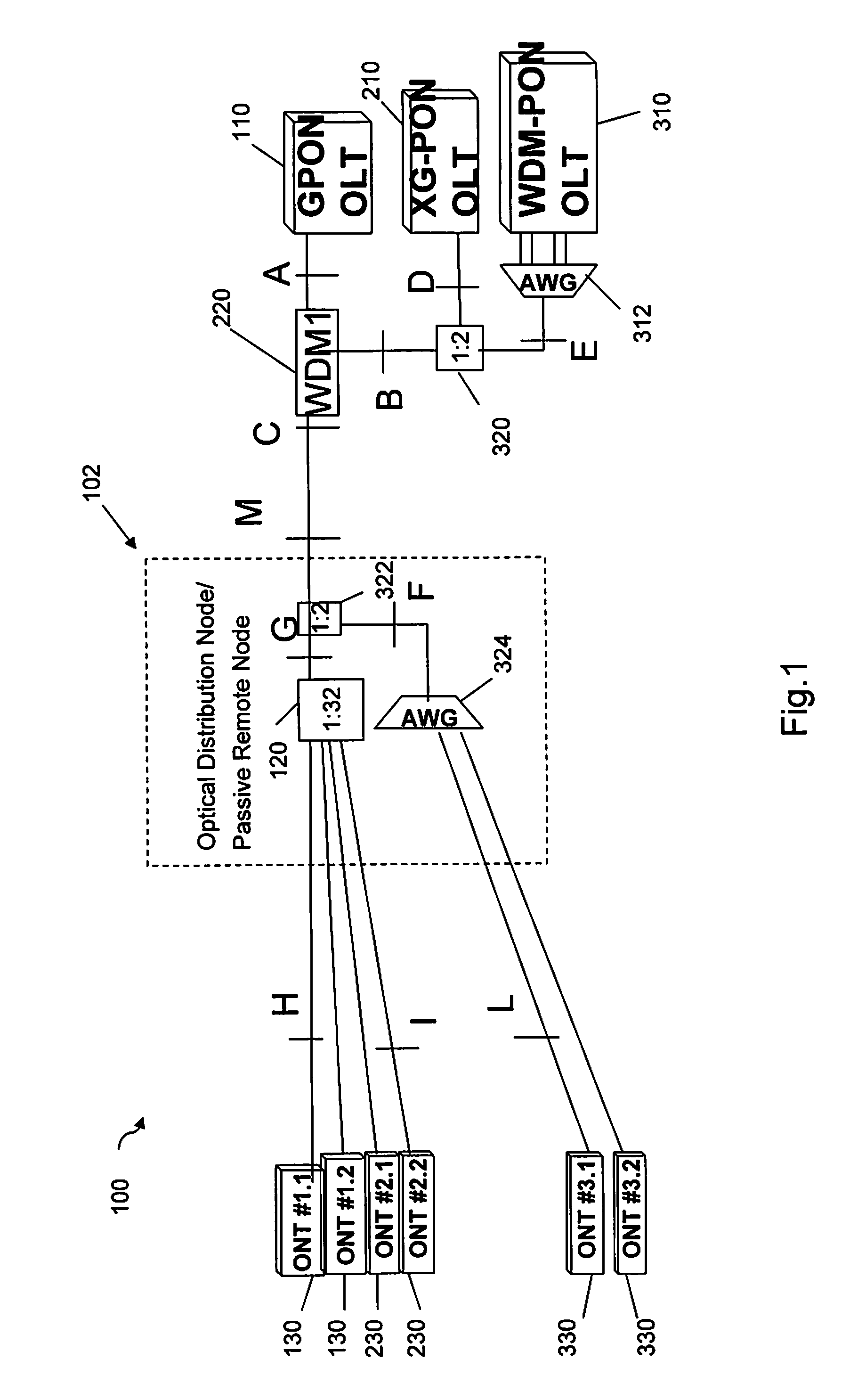
[0035]The present inventors have therefore proposed a suitable system architecture which would allow telecom operators to re-use the same fibre of a GPON system to upgrade to utilising 10G PON (e.g. in a first upgrade or provisioning step), and then to upgrade the same fibre network to WDM PON (e.g. in a second upgrade or provisioning step) whilst minimising the impact on existing equipment, minimising the disruption of the network required for each upgrade, and allowing continued use of the previous equipment after each upgrade.

[0036]FIG. 1 is a schematic diagram of an ...


PUM


Abstract

An optical network and a method of provisioning an optical network are described. The optical network includes a first passive optical network optical line terminal arranged to transmit a first optical signal at a first wavelength, coupled to a first port of a first optical filter arrangement, and a second passive optical network optical line terminal arranged to transmit a second optical signal at a second, different wavelength, coupled to a second port of the first optical filter arrangement. An optical coupler is connected between the second passive optical network line terminal and the second port of the first optical filter arrangement, for coupling a plurality of optical signals at a predetermined set of wavelengths from a third optical line terminal into the second port. A passive optical distribution node, for connection to a plurality of optical network terminations, is coupled to a third port of the first optical filter arrangement for distribution of optical signals between the optical line terminals and the plurality of optical network terminations. The first optical filter arrangement is arranged to pass optical signals at the first wavelength between the first port and the third port and to block optical signals at the second wavelength and the predetermined set of wavelengths between the first port and the third port, and the first optical filter arrangement is further arranged to pass optical signals at the second wavelength and the predetermined set of wavelengths between the second port and the third port and to block optical signals at the first wavelength between the second port and the third port. The second optical signal is at a faster rate than the first optical signal, and the second wavelength and the predetermined set of wavelengths are within an amplification band of a doped fibre amplifier.

Description

FIELD OF THE INVENTION[0001]The present invention relates to passive optical networks such as fibre access networks, and to associated methods of provisioning such networks.BACKGROUND OF THE INVENTION[0002]Optical fibre access networks provide communication facilities to subscribers utilizing an optical network of fibres extending from the subscribers premises to a central office of a network provider or operator. Typically a passive optical network (PON) having a point-to-multi-point architecture is used as this is considered the most cost effective solution.[0003]The passive optical network comprises an optical line terminal (OLT) at the central office which is coupled to the point-to-multi-point optical network of fibres. This fibre network uses a number of power splitters to distribute signals via optical fibre to each subscriber, such that an optical signal from the OLT will propagate to optical network terminations (ONT) for each subscriber. Different wavelengths are used for ...

Claims


Application Information

Patent Timeline
Patent Type & Authority Applications(United States)
IPC IPC(8): H04J14/02
CPCH04J14/0226H04J14/0282H04J14/0227H04J14/0252H04J14/0247H04J14/025H04J14/0246
Inventor CAVALIERE, FABIODAHLFORT, STEFAN
Owner TELEFON AB LM ERICSSON (PUBL)
Why Eureka
Try Eureka