
Model structure parameter decision method, parameter decision device, control device, and temperature adjustment device

a parameter decision and model structure technology, applied in automatic control, electric controllers, instruments, etc., can solve problems such as temperature difference, inability to achieve ideal non-interference, and low simpleness

Inactive Publication Date: 2009-01-15
ORMON CORP
View PDF6 Cites 3 Cited by
  • Summary
  • Abstract
  • Description
  • Claims
  • Application Information

AI Technical Summary

Benefits of technology

[0098]According to the present invention, the parameters of the model structure that is the gray box model where it has been conventionally believed to lack any method of deciding the parameters can be decided based on the output change generated when the input of the modeled object is changed.
[0099]Additionally, the parameters of the black box model can be used to decide the parameters of the model structure that is the gray box model, which makes it unnecessary to decide the parameters of the model structure in the trial-and-error manner as in the conventional technology.
[0100]Besides, the parameters of the resistance components of the respective elements of the model structure can be decided based on the output to the input of the modeled object, in other words, the characteristics of the modeled object.

Problems solved by technology

However, the interferential relationship of the controlled object 30 that is a predetermined condition of the example is not a simple and low-level matrix.
Therefore, a first model in this conventional example cannot realize an ideal non-interference.
The transfer of a heat quantity due to the interference results from a temperature difference.
Because such a relationship is not taken into account, the assumed model to be controlled generates a significant error, which gives a limit to a factor that can be eliminated through the inverse matrix of the non-interference control.
Therefore, the non-interference control in the conventional manner was often not applicable to practical use.

Method used


Image

  • Model structure parameter decision method, parameter decision device, control device, and temperature adjustment device
  • Model structure parameter decision method, parameter decision device, control device, and temperature adjustment device
  • Model structure parameter decision method, parameter decision device, control device, and temperature adjustment device

Examples


embodiment 1

Preferred Embodiment 1

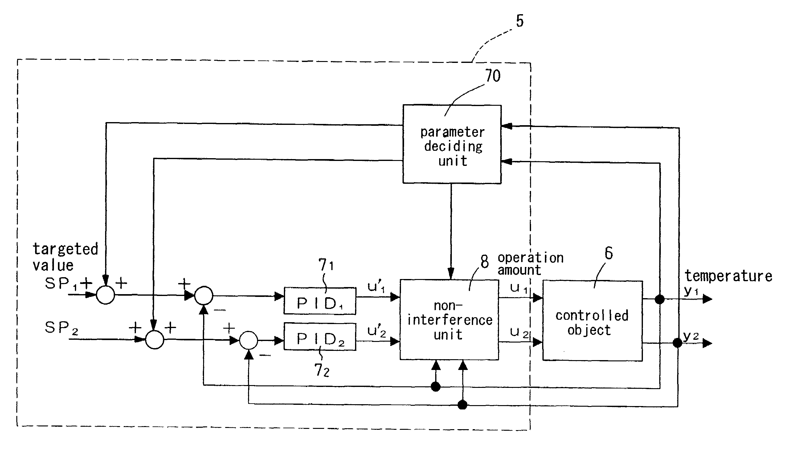
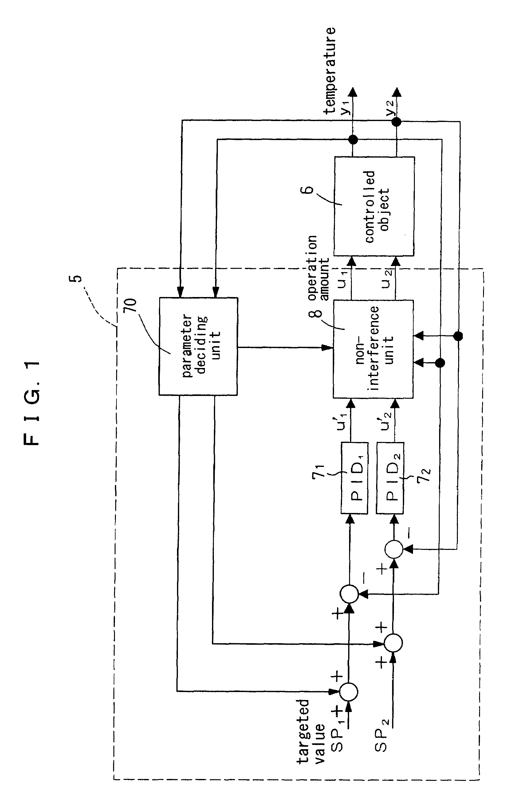
[0130]FIG. 1 shows a schematic constitution of a temperature control system provided with a temperature adjustment device 5 according to the present invention for performing non-interference control.

[0131]The temperature adjustment device 5 according to the present preferred embodiment performs the non-interference using the model structure proposed in the aforementioned Patent Document 1, and a parameter deciding unit 70 for deciding parameters of the model structure is incorporated therein. The parameter deciding unit 70 changes respective targeted temperatures SP1 and SP2 as described below when the parameters are decided.

[0132]The temperature adjustment device 5 comprises two PID control units 71 and 72 for respectively calculating and outputting operation amounts u1′ and u2′ based on differences between two detected temperatures y1 and y2 from a controlled object 6 and respective targeted temperatures SP1 and SP2, a non-interference unit 8 for executing th...

embodiment 2

Preferred Embodiment 2

[0223]The foregoing preferred embodiment was applied to the model structure having the two inputs and the two outputs. Below described is a preferred embodiment 2 of the present invention that is applied to a model structure having N inputs and N outputs (N is a natural number of at least two).

[0224]In the present preferred embodiment, the model structure shown in FIG. 21 is applied to a plurality of channels. As shown in FIG. 4, a plurality (n) of model elements 601-60n are set as the first-order lag system in which steady gains Ki-Kn and time constants T1-Tn are used, and a plurality (n−1) of feedback elements 6112-61(n-1)n are set as the fixed values in which resistances θ12-θ(n-1)n are used. In FIG. 4, P1-Pn denote inputs, and T1-Tn denote outputs.

[0225]Here, first, the parameters are obtained in the steady state in view of the steady-state properties.

[0226]Provided that a transfer functions G(s) of the controlled object of the thermal system is the first-o...

embodiment 3

Preferred Embodiment 3

[0268]In the aforementioned preferred embodiment 2, it is necessary for the user to set the thermal capacity C in order to decide all of the parameters in the model structure 1-1 as in the model prediction control, which is troublesome.

[0269]So, in this preferred embodiment of the present invention, it is unnecessary for the user to set the thermal capacities C1-Cn which regulate the time constants T1-Tn=C1·θ1-Cn·θn of the respective channels in the model structure shown in FIG. 4, the parameters are obtained from a maximum tilt R in the step response waveform of the controlled object 6.

[0270]In the response waveform of the output y of the controlled object shown in FIG. 15(b) to the stepwise input u shown in FIG. 15(a), the maximum tilt R is expressed with the steady gain K and the time constant T in the following expression.

R=K / T

[0271]Here, because the steady gain K can be expressed with the thermal resistance θ as described above, and the time constant T ca...


PUM


Abstract

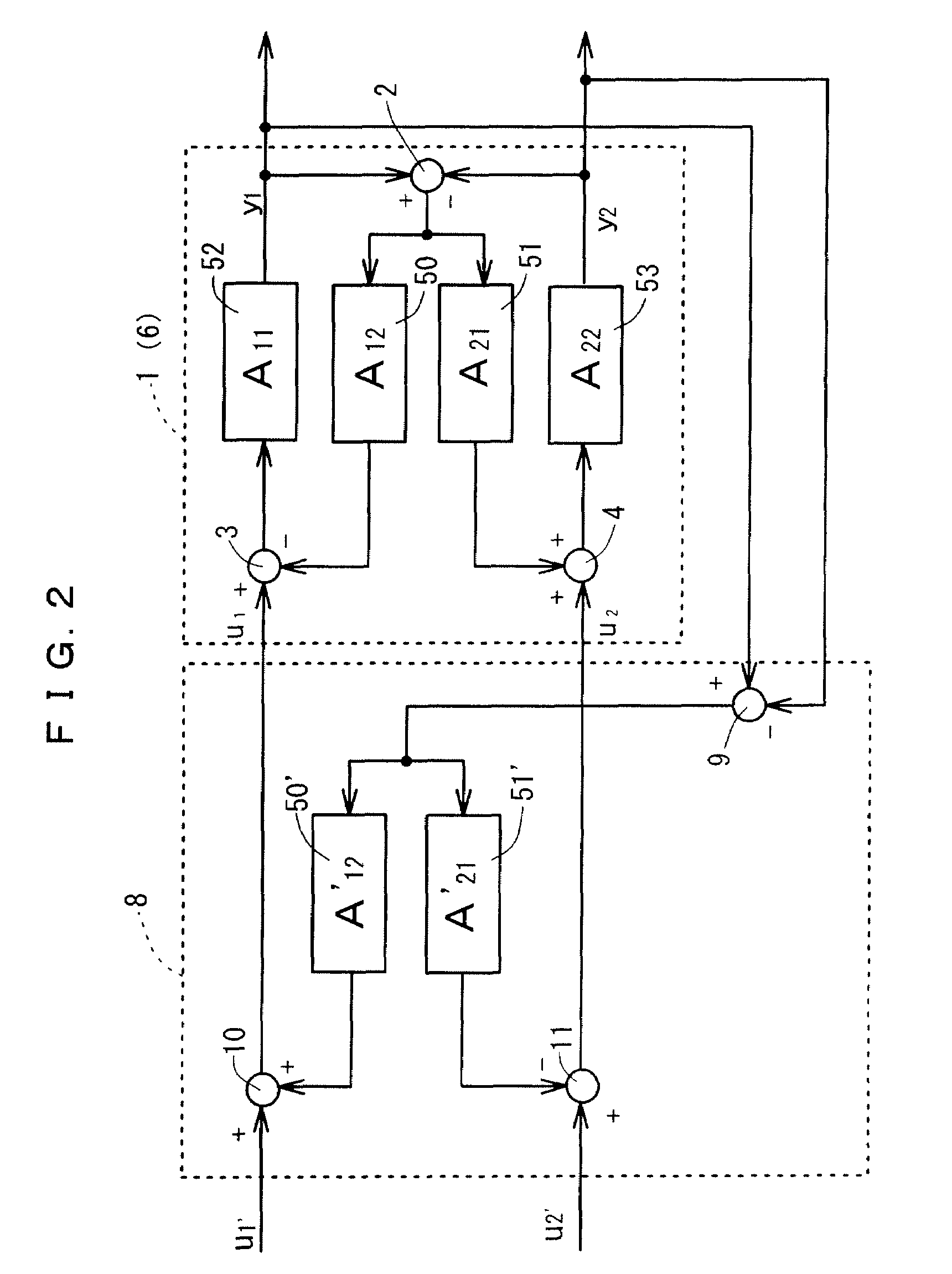
[Problem] To easily decide parameters of a model structure of a controlled object suitable for non-interference control.[Means for Solving Problems] Parameters K and T of a model structure (A structure) comprising a plurality of inputs and a plurality of outputs, wherein a difference on the output side is fed back to the input side, are calculated based on parameters a and b of a black box model (P structure) calculated through system identification or the like in accordance with predetermined conversion expressions K=f(a,b) and T=f(a,b).

Description

FIELD OF THE INVENTION[0001]The present invention relates to a method and a device for deciding parameters of a model structure suitable for a model such as an object to be measured and a controlled object, and a control device and a temperature adjustment device in which the method and the device are used, more particularly to a method and a device for deciding parameters of a model structure suitable for controlling an object in which an interference exists, and a control device and a temperature adjustment device in which the method and the device are used.BACKGROUND OF THE INVENTION[0002]There is the non-interference PID control shown in FIG. 20 (for example, see the Non-Patent Document 1) as an example of the conventional technology for realizing non-interference control with respect to, for example, a controlled object comprising a plurality of inputs and outputs where an interference exists between them, in other words, a controlled object comprising a plurality of operation ...

Claims


Application Information

Patent Timeline
Patent Type & Authority Applications(United States)
IPC IPC(8): G05B13/02
CPCG05B17/02
Inventor NANNO, IKUO
Owner ORMON CORP
Learn More