Infrared suppression system with spiral septum

a technology of infrared suppression and spiral septum, which is applied in the direction of machines/engines, mechanical equipment, transportation and packaging, etc., can solve the problems of reducing the velocity of exhaust flow, re-ingesting into the engine, and limited conventional ir suppressor systems, so as to minimize the aerodynamic impact of aircraft, minimize the impact of exhaust impingement, and effectively hide and cool the exhaust components

US20090025362A1Inactive Publication Date: 2009-01-29SIKORSKY AIRCRAFT CORP
8 Cites 16 Cited by

Patent Information

Authority / Receiving Office
US · United States
Current Assignee / Owner
Publication Date
2009-01-29
Estimated Expiration
Not applicable · inactive patent

Smart Images

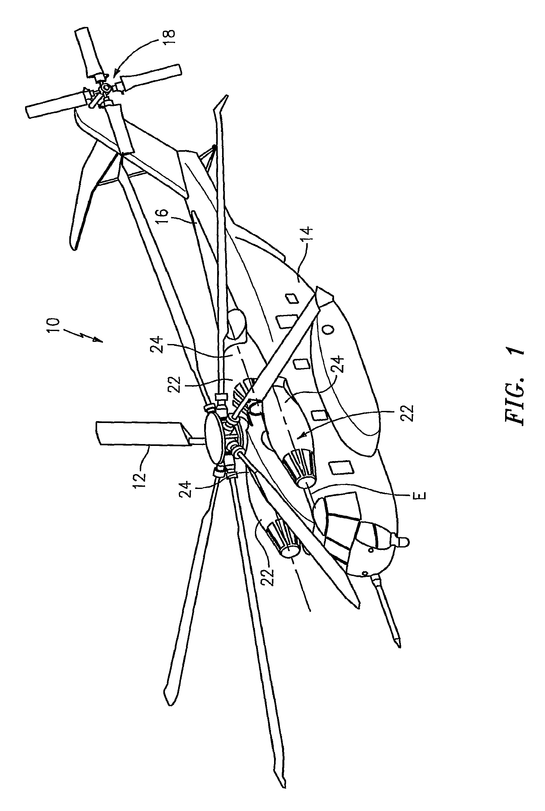
  • Figure 1
    Figure 1
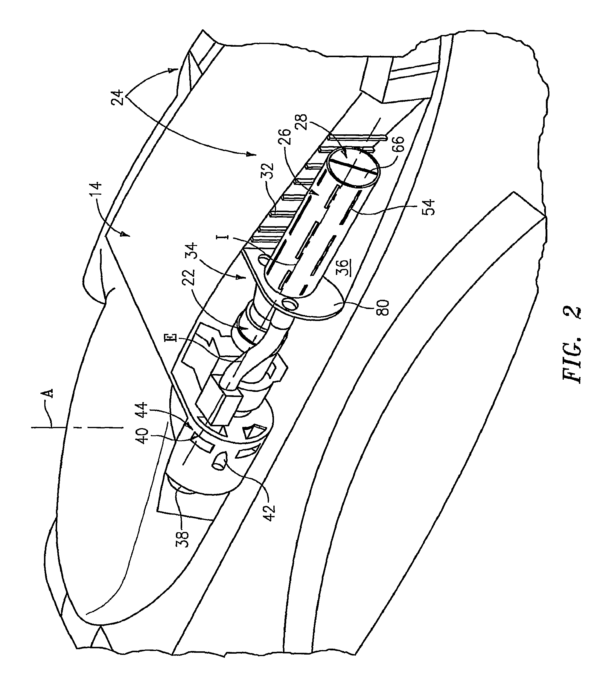
  • Figure 2
    Figure 2
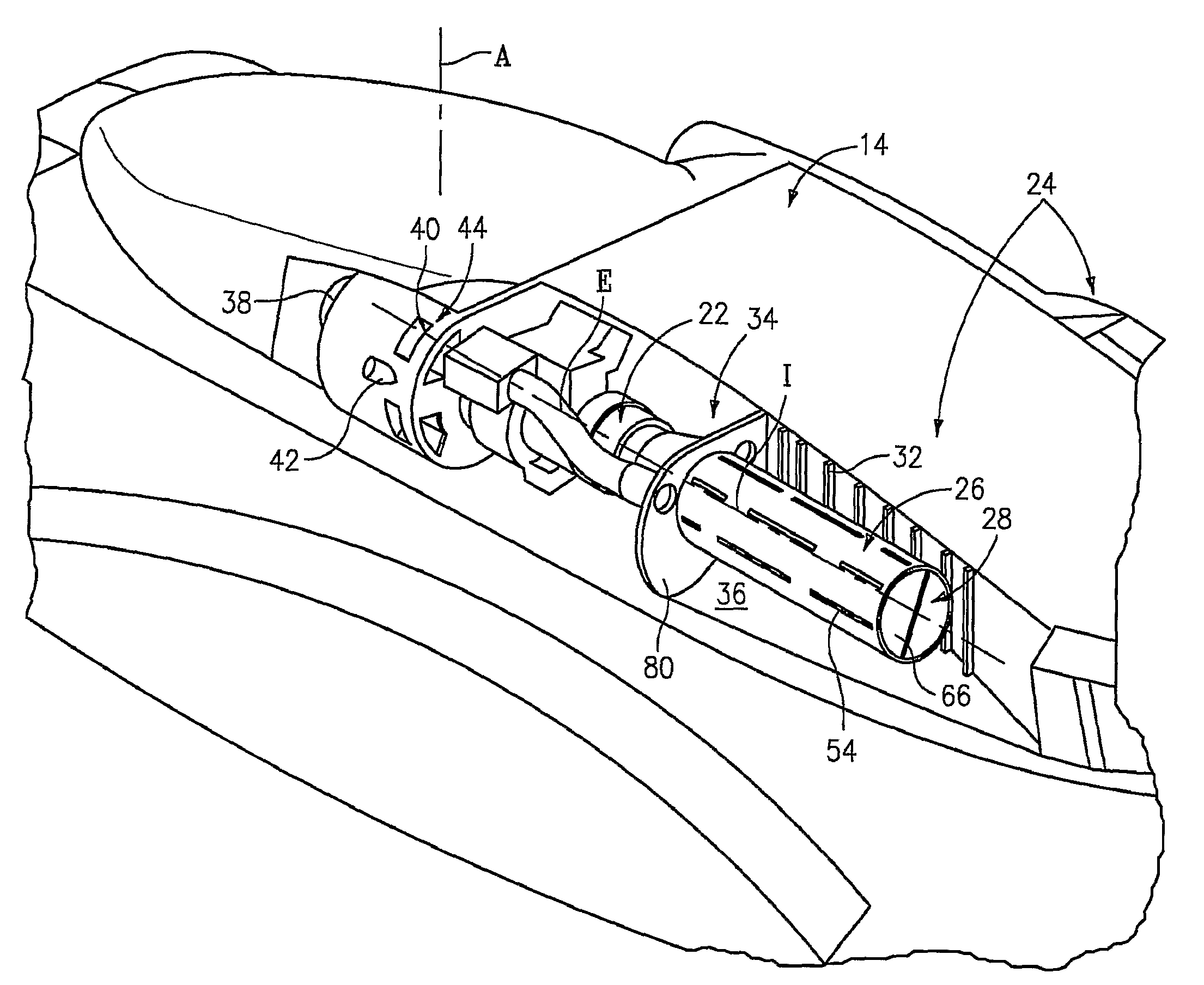
  • Figure 3
    Figure 3
Patent Text Reader

Abstract

An InfraRed Suppression System (IRSS) includes a double-walled exhaust duct and double walled septum. The double walled structure provides a flow path for secondary (non-exhaust gas) cooling air flow to slots along the surfaces exposed to exhaust gases. Exhaust gas flow past these slots draws cooling air across the duct and septum surfaces. This flow cools the surfaces close to the slots and mixes with exhaust gasses downstream to cool the exhaust plume. The septum in the shape of a helix rotating fully blocks line-of-sight to the turbine exit from the aft of the aircraft. The exhaust duct is intended to be shrouded by an aerodynamic fairing which provides an aerodynamic contour which minimizes aerodynamic impact on the aircraft.
Need to check novelty before this filing date? Find Prior Art

Description

[0001] The present application claims priority to U.S. Provisional Patent Application Ser. No. 60 / 777,658, filed Feb. 27, 2006.BACKGROUND OF THE INVENTION

[0002] The present invention relates to an infrared suppression system (IRSS), and more particularly to an infrared suppression system which uses a film-cooled spiral septum within an exhaust duct to mask the engine exhaust and reduce the overall infrared signature of an aircraft.

[0003] The exhaust plume and plume-heated surfaces from a gas turbine engine may be a source of infrared (IR) energy which may be detected by heat seeking missiles and / or various forms of infrared imaging systems for targeting / tracking purposes. With respect to the former, a heat-seeking missile may obtain directional cues from infrared energy generated by the engine exhaust such that the amount of infrared energy is one of the primary determining factors of a missile's accuracy, and consequently, lethality. Regarding the latter, infrared imaging systems dete...

Examples

Embodiment Construction

[0025]FIG. 1 schematically illustrates a rotary-wing aircraft 10 having a main rotor system 12. The aircraft 10 includes an airframe 14 having an extending tail 16 which mounts an anti-torque tail rotor system 18. The main rotor system 12 is driven about an axis of rotation A through a transmission (illustrated schematically at 20) by one or more gas turbine engines 22. Although a particular helicopter configuration is illustrated in the disclosed embodiment, other configurations and / or machines will also benefit from the present invention.

[0026]The rotary wing aircraft 10 also includes an InfraRed Suppression System (IRSS) 24 in communication with each gas turbine engine 22. The IRSS 24 suppresses the IR signature radiating from the high-temperature exhaust generated by the gas turbine engines 22. In the context used herein, “suppress” means that the TR signature emanating from the gas turbine engine 22 is reduced below that expelled by the gas turbine engine 22 after passage throu...