Method for directing power to a hot swapped circuit board

a technology of hot swapping and circuit boards, applied in the direction of power supply for data processing, electrical apparatus construction details, instruments, etc., can solve the problems that neither the component nor the user can be damaged or injured by removing or installing

Inactive Publication Date: 2009-02-05
IBM CORP
View PDF23 Cites 17 Cited by
  • Summary
  • Abstract
  • Description
  • Claims
  • Application Information

AI Technical Summary

Benefits of technology

[0012]The present invention also provides a method comprising the steps of forming a circuit between cassette flex circuitry and chassis flex circuitry whenever a cassette including the cassette flex circuitry is placed in an operable position, relative to the chassis including chassis flex circuitry; using the circuit to detect whether a user is handling the cassette; providing power from the chassis to the cassette in response to detecting that the cassette is simultaneously in the operable position and a user is not handling the cassette; and allowing the assignment of processing jobs to an electronic component within the cassette when the cassette is provided with power. Preferably, the method further comprises allowing the electronic component within the cassette to complete any existing processing jobs and disallowing the assignment of new processing jobs to the electronic component in response to detecting that a user is handling the cassette; and halting power provided from the chassis to the cassette in response to detecting that the electronic component has no more processing jobs.

Problems solved by technology

In addition, all connections need to be designed such that neither the component nor the user can be damaged or injured by removing or installing it.

Method used


Image

  • Method for directing power to a hot swapped circuit board
  • Method for directing power to a hot swapped circuit board
  • Method for directing power to a hot swapped circuit board

Examples


Embodiment Construction

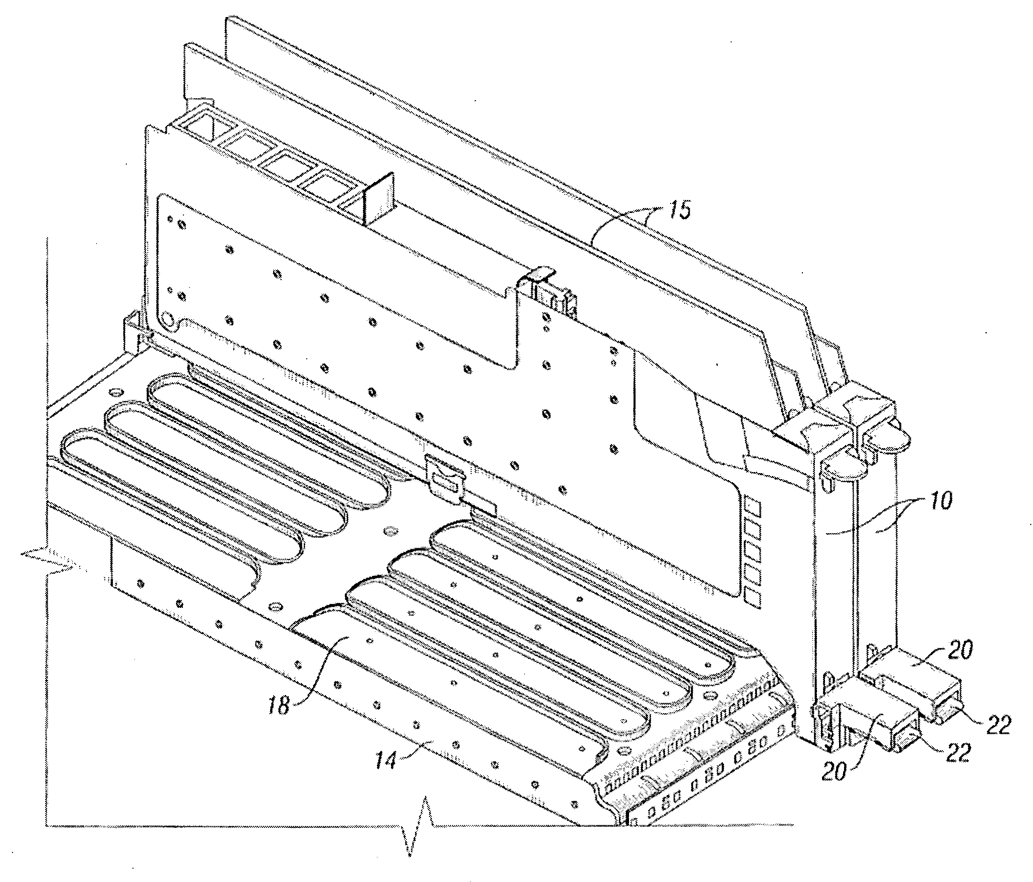
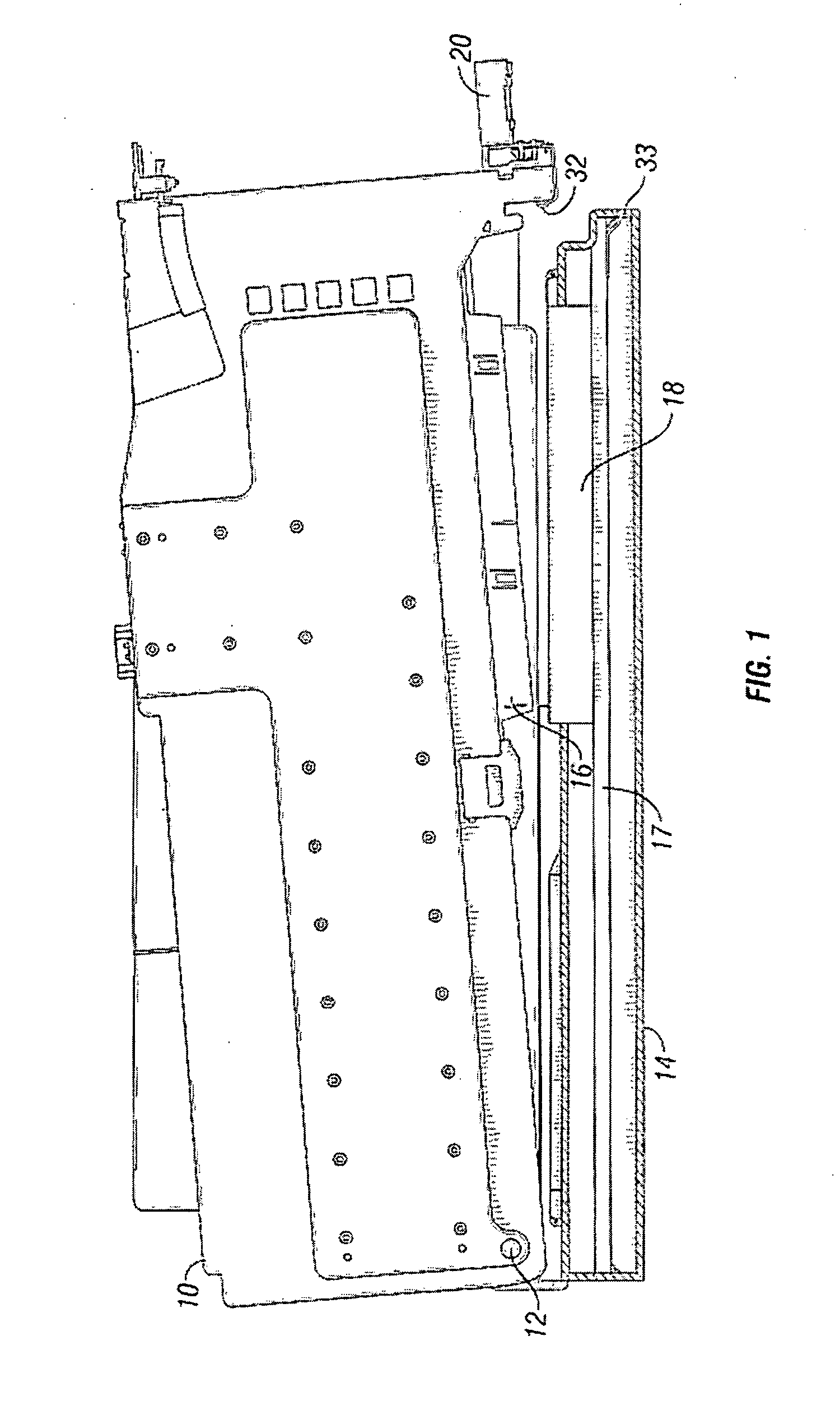
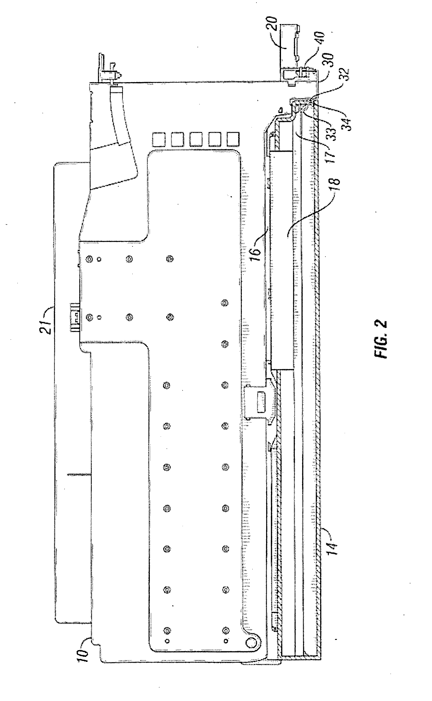
[0020]The present invention provides a chassis that receives a cassette, supplies power to the cassette, and communicates with electronic components on the cassette, such as an electronic circuit, board. The chassis comprises a first electronic circuit board with a first connector to receive a second electronic circuit board with a second connector. The cassette and the chassis selectively cooperate in a predetermined manner to align the second connector with the first connector. The first electronic circuit board has a first connector that receives a second electronic circuit board and supplies power to the second electronic circuit board. A typical example of a first electronic circuit board is a motherboard.

[0021]The chassis further comprises chassis flex circuitry including a pair of contacts arranged to contact cassette flex circuitry when the cassette is received by the chassis. The cassette flex circuitry and the chassis Hex circuitry complete a circuit when there is contact ...


PUM


Abstract

Method for controlling power and communications between to an electronic circuit board. A chassis includes a first electronic circuit board with a first connector and a cassette includes a second electronic circuit board with a second connector. When the cassette is received by the chassis, chassis flex circuitry and cassette flex circuitry come into contact to complete a circuit between the components. Closing the circuit indicates to a controller that the cassette is properly secured to the chassis and that a user is not attempting removal of the cassette. The controller instructs a power source to provide power to the second electronic circuit board through the first connector. When the circuit is broken by a user, the controller causes the completion of operations on the second electronic circuit board and causes the power source to stop supplying power to the second electronic circuit board.

Description

[0001]This nonprovisional application is a divisional application of US nonprovisional application Ser. No. 11 / 679,703 filed on Feb. 27, 2007.BACKGROUND OF THE INVENTION[0002]1. Field of the Invention[0003]The present invention relates to methods for directing power to a hot-swappable computer component when inserted, and safely powering down the component prior to removal.[0004]2. Description of the Related Art[0005]Hot swappable components have become commonplace in computer systems. Server systems often use hot swappable memory, hard drives, and various pieces of hardware commonly referred to as Peripheral Component Interconnect (PCI) cards. Hot swapping may involve the removal of a piece of hardware, or the insertion of a piece of hardware, or both while the computer is on and functioning. While the following discussion refers to PCI cards, the problems presented are equally applicable to any other hot swappable electronic circuit board.[0006]Computer systems that support hot sw...

Claims


Application Information

Patent Timeline
Patent Type & Authority Applications(United States)
IPC IPC(8): H05K7/18H05K7/14G06F13/00
CPCG06F13/4081H05K7/1414H05K1/147G06F1/16G06F1/1601G06F1/26G06F13/40
Inventor KERRIGAN, BRIAN MICHAEL
Owner IBM CORP
Why Eureka
Try Eureka