Polyaxial bone screw with helically wound capture connection

a technology of helically wounding and bone screws, applied in the field of polyaxial bone screws, can solve the problems of unsatisfactory, difficult or impossible to do, and difficult to rigidly fix to each other and into the desired position, and achieve the effect of preventing unintentional disassembly, convenient and convenient use, and adequate friction or gripping surfaces

Inactive Publication Date: 2009-02-05
JACKSON
View PDF2 Cites 15 Cited by
  • Summary
  • Abstract
  • Description
  • Claims
  • Application Information

AI Technical Summary

Benefits of technology

[0009]It is an object of the invention to overcome one or more of the problems described above. Further objects of the invention include: providing a polyaxial bone screw with features that provide adequate frictional or gripping surfaces for bone implantation tools and may be readily, securely fastened to each other and to bone. Also, if the implant should slip or become loose for some reason, an object of the invention is to provide an implant wherein all of the parts remain together and do not separate. Furthermore, it is an object of the invention to provide a lightweight, low profile polyaxial bone screw that assembles in such a manner that the components cooperate to create an overall structure that prevents unintentional disassembly.
[0012]The bone screw assembly also includes an integral one piece contiguously closed ring-like retainer structure that has an internal surface with a helically wound structure thereon, such as a thread. The thread of the retainer structure is sized and shaped to mate with the thread of the shank capture structure when the retainer structure and the capture structure are coaxially aligned within the head cavity, thereby securing the retainer structure to the capture structure.
[0013]The external surface of the retainer structure is configured to be in slidable mating engagement with the surface defining the cavity of the head. Preferably, the retainer structure external surface and the mating head inner surface are substantially spherical. However, it is noted that the mating surfaces may be of another shape, such as conical or tapered, especially for the head cavity inner surface. The cooperating shapes of the retainer external surface and the head inner surface enable selective angular positioning of the shank body with respect to the head.
[0017]In certain embodiments, both the capture structure and the retainer structure may include tool seating surfaces that extend radially in the same plane when the capture structure and the retainer structure are mated. In such embodiments, the two tool seating surfaces and the shank tool engagement surfaces partially define a recess for receiving a driving tool engaged with the tool engagement surfaces. When engaged, the driving tool is in contact with both tool seating surfaces, thereby seating the tool lower relative to the tool engagement surfaces and providing additional frictional gripping surface when the shank body is driven into bone.

Problems solved by technology

This is sometimes very difficult or impossible to do.
Consequently, heavy, bulky implants are undesirable and lighter implants with a relatively small profile both in height and width are more desirable.
However, a drawback to smaller, lighter implants is that they may be more difficult to rigidly fix to each other and into a desired position.
Lack of bulk may also mean lack of strength, resulting in slippage under high loading.
A further drawback of smaller components is that they may be difficult to handle during surgery because of their small size, failing to provide adequate driving or gripping surfaces for tools used to drive the shank into bone.
One undesirable attribute of some of the swivel-head implants is the need for a multitude of components that may loosen or even disassemble within the body.
It is most undesirable for components to be free to move around in the body after the completion of surgery.
Loosening of components relative to each other may result in related undesirable movement of the bone or vertebra that the implant was intended to stabilize.

Method used


Image

  • Polyaxial bone screw with helically wound capture connection
  • Polyaxial bone screw with helically wound capture connection
  • Polyaxial bone screw with helically wound capture connection

Examples


Embodiment Construction

[0048]As required, detailed embodiments of the present invention are disclosed herein; however, it is to be understood that the disclosed embodiments are merely exemplary of the invention, which may be embodied in various forms. Therefore, specific structural and functional details disclosed herein are not to be interpreted as limiting, but merely as a basis for the claims and as a representative basis for teaching one skilled in the art to variously employ the present invention in virtually any appropriately detailed structure.

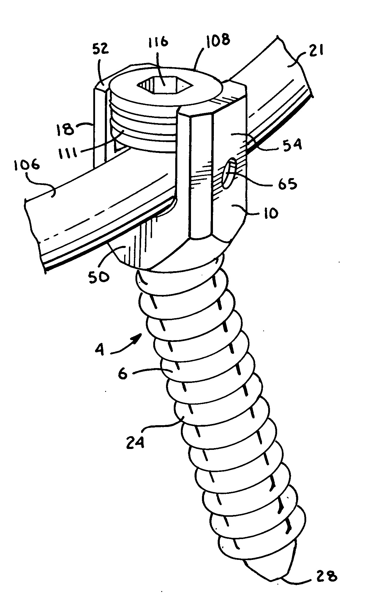
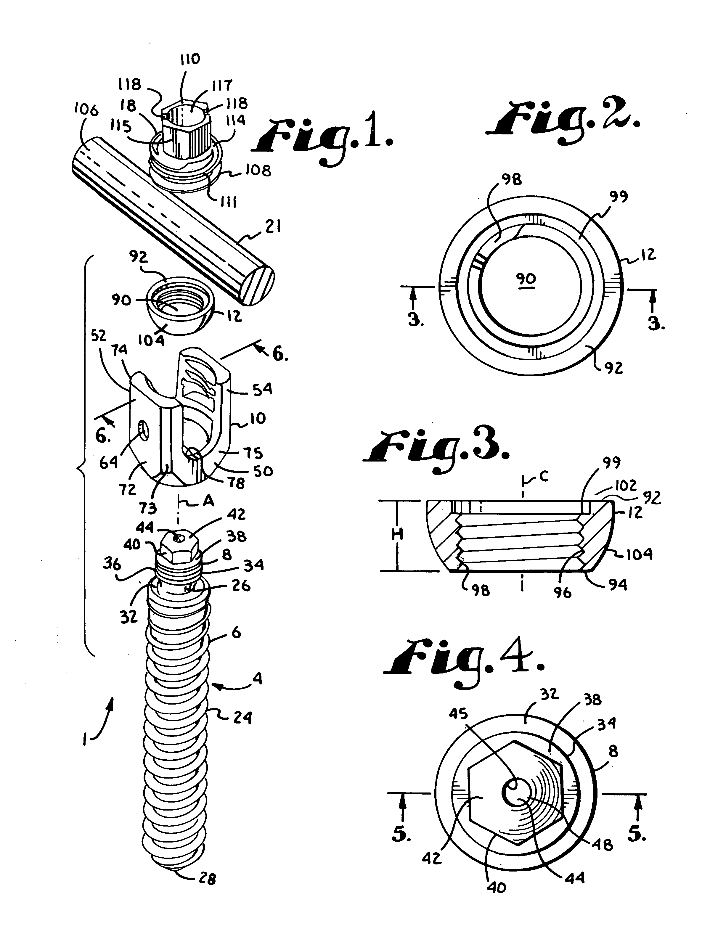
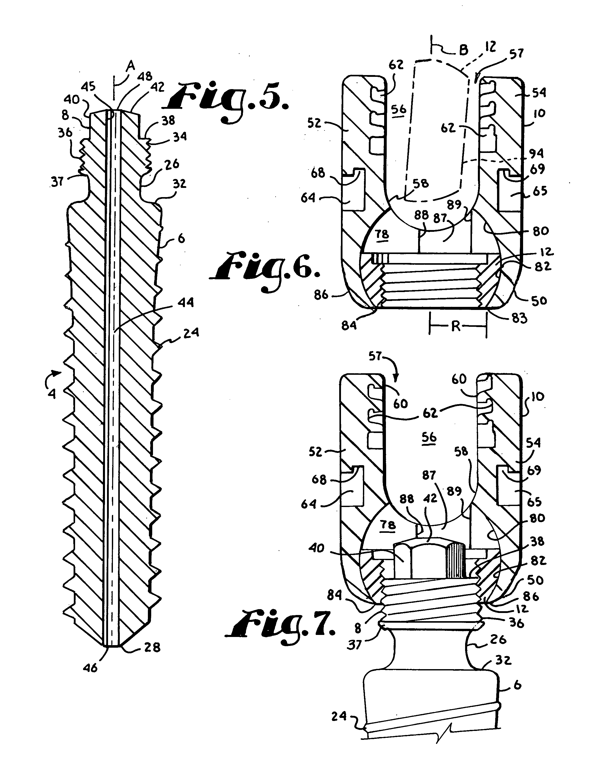
[0049]In FIGS. 1-11 the reference number 1 generally represents a first embodiment of a polyaxial bone screw apparatus or assembly according to the present invention. The assembly 1 includes a shank 4 that further includes a body 6 integral with an upwardly extending capture structure 8; a head 10; and a closed integral retainer structure or ring 12. The shank 4, head 10 and retainer structure 12 preferably are assembled prior to implantation of the shank bod...


PUM


Abstract

A polyaxial bone screw assembly includes a threaded shank body having an upper capture structure, a head and a closed retainer ring. The external capture structure surface and retainer ring internal bore surface are both threaded for rotatable attachment within a cavity of the head. The head has a U-shaped cradle defining a channel for receiving a spinal fixation rod. The head channel communicates with the cavity and further with a restrictive opening that allows for loading the capture structure into the head but prevents passage of the closed retainer ring out of the head. The retainer ring has an external substantially spherical surface that mates with an internal surface of the head, providing a ball joint, enabling the head to be disposed at an angle relative to the shank body. The threaded capture structure or the closed retainer structure includes a tool engagement formation and gripping surfaces for non-slip engagement by a tool for driving the shank body into bone.

Description

CROSS REFERENCE TO RELATED APPLICATIONS[0001]This application is a divisional of U.S. application Ser. No. 10 / 986,377, filed Nov. 10, 2004.BACKGROUND OF THE INVENTION[0002]The present invention is directed to polyaxial bone screws for use in bone surgery, particularly spinal surgery. Such screws have a head that can swivel about a shank of the bone screw, allowing the head to be positioned in any of a number of angular configurations relative to the shank.[0003]Many spinal surgery procedures require securing various implants to bone and especially to vertebrae along the spine. For example, elongate rods are often utilized that extend along the spine to provide support to vertebrae that have been damaged or weakened due to injury or disease. Such rods must be supported by certain vertebrae and support other vertebrae.[0004]The most common mechanism for providing vertebral support is to implant bone screws into certain bones which then in turn support the rod or are supported by the r...

Claims


Application Information

Patent Timeline
Patent Type & Authority Applications(United States)
IPC IPC(8): A61B17/04
CPCA61B17/7011A61B17/7037A61B17/7032A61B17/7028A61B2090/037A61B17/7035A61B17/8625A61B17/864
Inventor JACKSON
Owner JACKSON
Why Eureka
Try Eureka