Disc drive apparatus

a disc drive and drive shaft technology, applied in the direction of electric apparatus casings/cabinets/drawers, casings/cabinets/drawers, instruments, etc., can solve the problems of physical looseness, increased manufacturing costs, and noise produced if any mechanical system is loosened

Inactive Publication Date: 2009-02-12
KK TOSHIBA
View PDF12 Cites 3 Cited by
  • Summary
  • Abstract
  • Description
  • Claims
  • Application Information

AI Technical Summary

Benefits of technology

[0009]The optical disc drive apparatus is vibrated as the motor vibrates and the disc rotates eccentrically. Therefore, noise is produced if any mechanical system is loosened. Therefore, as described in Jpn. Pat. Appln. KOKAI Publication No. 2005-190595, for example, there is provided an apparatus in which a pivotal portion of a chassis mount is elastically deformable so that vibration can be absorbed to reduce noise by elastically engaging the pivotal portion with a support portion of a housing.

Problems solved by technology

Therefore, noise is produced if any mechanical system is loosened.
In this case, however, the manufacturing cost is increased inevitably.
In some cases, moreover, physical looseness may be generated by contraction or expansion of the components that is caused by a temperature change.
Alternatively, the components may engage with one another and cause an overload, which hinders some operations.
In a low-temperature environment, therefore, the housing and the chassis mount engage with each other owing to a difference in the amount of linear thermal expansion, so that the chassis mount may possibly be prevented from moving smoothly.
Therefore, looseness may be caused depending on the combination of components or operations may be hindered by an overload.

Method used


Image

  • Disc drive apparatus
  • Disc drive apparatus
  • Disc drive apparatus

Examples


Embodiment Construction

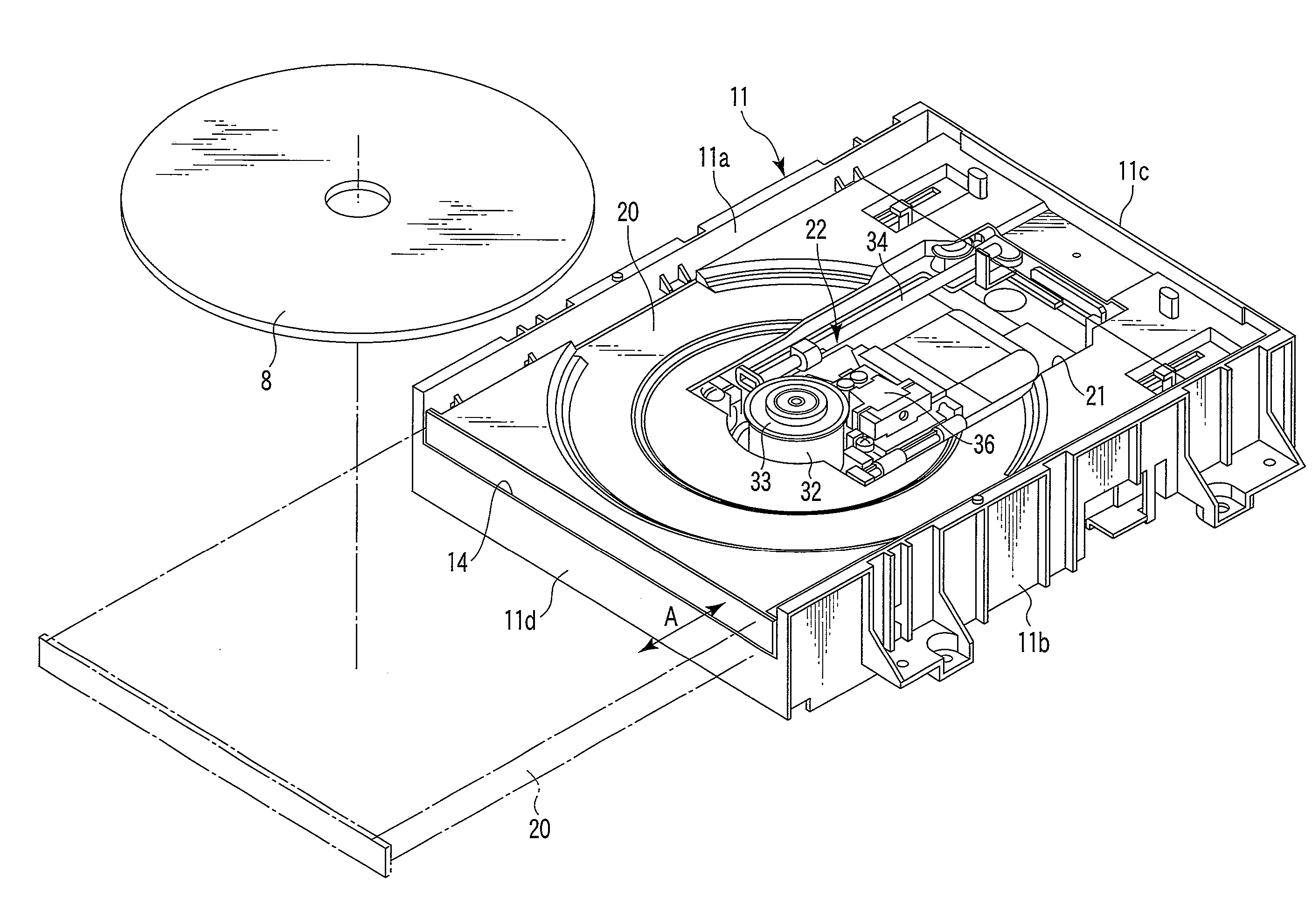
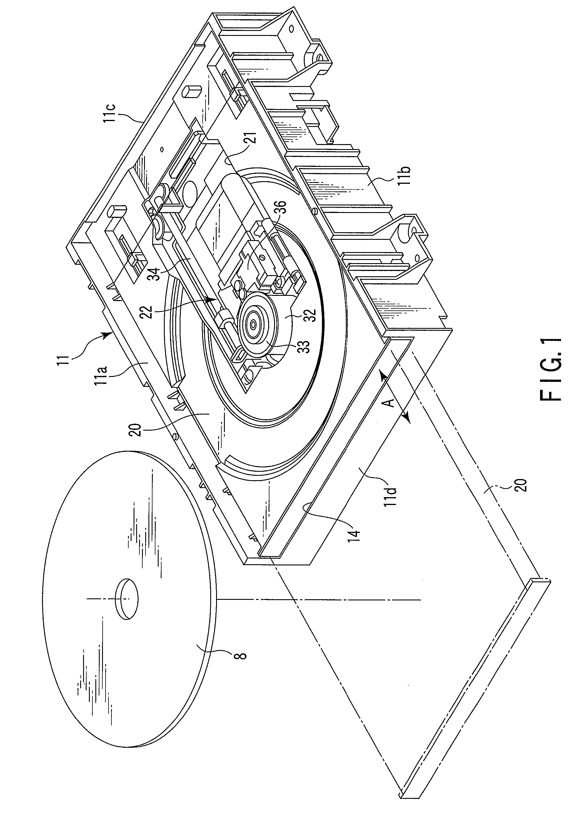
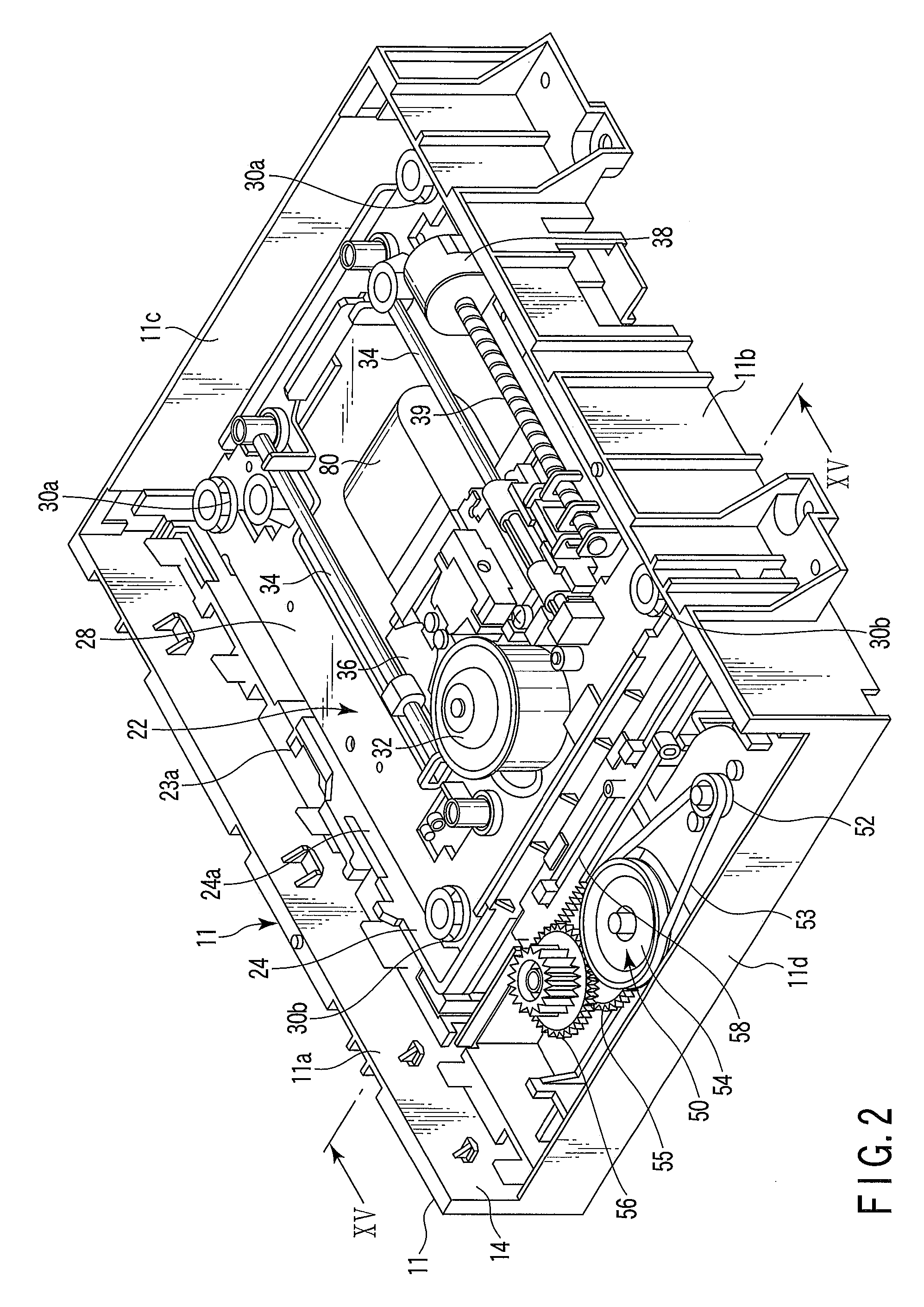
[0035]Various embodiments according to the invention will be described hereinafter with reference to the accompanying drawings. In general, according to one embodiment of the invention, there is provided a disc drive apparatus comprising: a main frame including sidewalls opposed to each other and a first guide and a second guide disposed individually on the sidewalls and opposed to each other; a recording medium holder which is configured to hold a disc recording medium and is arranged on the main frame for movement between an unloaded position in which the holder projects out of the main frame and an operating position in which the recording medium is configured to be driven in a predetermined position in the main frame; a medium drive section including a motor which is configured to support and rotate the recording medium and a head portion configured to process information on the recording medium and arranged for ascent and descent between a retracted position in which the record...


PUM

PropertyMeasurementUnit
movementaaaaaaaaaa
flexibleaaaaaaaaaa
physical loosenessaaaaaaaaaa

Abstract

According to one embodiment, a disc drive apparatus includes a main frame having sidewalls and first and second guides disposed on the sidewalls and opposed to each other, a recording medium holder configured to hold a disc recording medium, a medium drive section, and an ascent / descent retaining member which supports the medium drive section and is attached to the main frame for ascent and descent. The retaining member includes a pair of arm portions, a connecting portion which connects respective one-end portions of the arm portions, pivotal portions arranged on the respective other end portions of the arm portions and supported on the sidewalls, and first and second engaging portions disposed on the respective one-end portions of the arm portions for engagement with the first and second guides, respectively. The first guide is formed of a leaf spring and configured to urge the retaining member toward the second guide.

Description

CROSS-REFERENCE TO RELATED APPLICATIONS[0001]This application is based upon and claims the benefit of priority from Japanese Patent Application No. 2007-208478, filed Aug. 9, 2007, the entire contents of which are incorporated herein by reference.BACKGROUND[0002]1. Field[0003]One embodiment of the present invention relates to a disc drive apparatus for processing information on a disc recording medium.[0004]2. Description of the Related Art[0005]In recent years, optical discs have been widespread for use as disc recording media, including the read-only type represented by a DVD-ROM, the one-time recording type represented by a DVD-R, and the rewritable type represented by a DVD-RAM and DVD-RW that can be utilized for externally attached memories for computers, recording and playback video systems, etc.[0006]An optical disc drive apparatus that records or reproduces information to or from an optical disc is provided with a housing having a disc loading slot and a disc tray that loads...

Claims


Application Information

Patent Timeline
Patent Type & Authority Applications(United States)
IPC IPC(8): G11B17/03G11B17/04
CPCG11B17/0288G11B33/08G11B17/056G11B17/03G11B25/04G11B33/02G11B33/12
Inventor YAMAGUCHI, TOMOO
Owner KK TOSHIBA
Why Eureka
Try Eureka