
Lubricant composition, speed reduction gear using the same, and electric power steering apparatus using the same

a technology of speed reduction gear and composition, applied in mechanical devices, gearing details, transportation and packaging, etc., can solve the problems of low productivity, and affecting the effect of noise production

Inactive Publication Date: 2010-05-04
NIPPON POLYURETHANE IND CO LTD +1
View PDF26 Cites 0 Cited by
  • Summary
  • Abstract
  • Description
  • Claims
  • Application Information

AI Technical Summary

Benefits of technology

The lubricant composition effectively reduces noise and steering torque in speed reduction gears, improving driving comfort while maintaining productivity and reducing manufacturing costs.

Problems solved by technology

At the time of forward / backward rotation of the gears and in a case where an automobile travels on a punishing road such as a stone pavement to cause input of a reaction force from a tire, for example, however, a teeth striking sound may, in some cases, be produced due to the backlash.
When the teeth striking sound is transmitted as noise to the inside of the automobile, an uncomfortable feeling is given to a driver.
In such a method, however, the productivity is significantly low.
Another problem is that even if the by-layer assembly is carried out, there occurs nonuniformity of a steering torque due to offcenter of a shaft of a worm wheel.
The same problems exist in not only speed reduction gears in electric power steering apparatuses but also general speed reduction gears having the small and large gears.
However, the configuration of the above-mentioned speed reduction gear becomes significantly complicated, resulting in raised manufacturing cost.

Method used


Image

  • Lubricant composition, speed reduction gear using the same, and electric power steering apparatus using the same
  • Lubricant composition, speed reduction gear using the same, and electric power steering apparatus using the same
  • Lubricant composition, speed reduction gear using the same, and electric power steering apparatus using the same

Examples


example 1-1

[0098]Used as aliphatic polyester polyol A was ester of butylene glycol and adipic acid (a number-average molecular weight Mn=2000, a hydroxyl value 56). Used as aromatic polyester polyol B was ester of hexamethylene glycol and phthalic acid (a number-average molecular weight Mn=1000, a hydroxyl value 112).

[0099]226 g of the aliphatic polyester polyol, 226 g of the aromatic polyester polyol, 490 g of isooctane serving as a dispersion medium, and 19 g of a dispersion stabilizer [N-5741 manufactured by NIPPON POLYURETHANE INDUSTRY CO., LTD.] were fed into a 1 liter flask while supplying nitrogen to the flask. The weight ratio of the aliphatic polyester polyol A to the aromatic polyester polyol B was set to A / B=50 / 50.

[0100]Agitation was then started. 0.003 g of di-n-butyltin dilaurate serving as a catalyst was added with the aliphatic polyester polyol and the aromatic polyester polyol dispersed in isooctane, and 116 g of hexamethylene diisocyanate serving as polyisocyanate was further ...

example 1-[UNK]-13

Example 1-2˜1-13

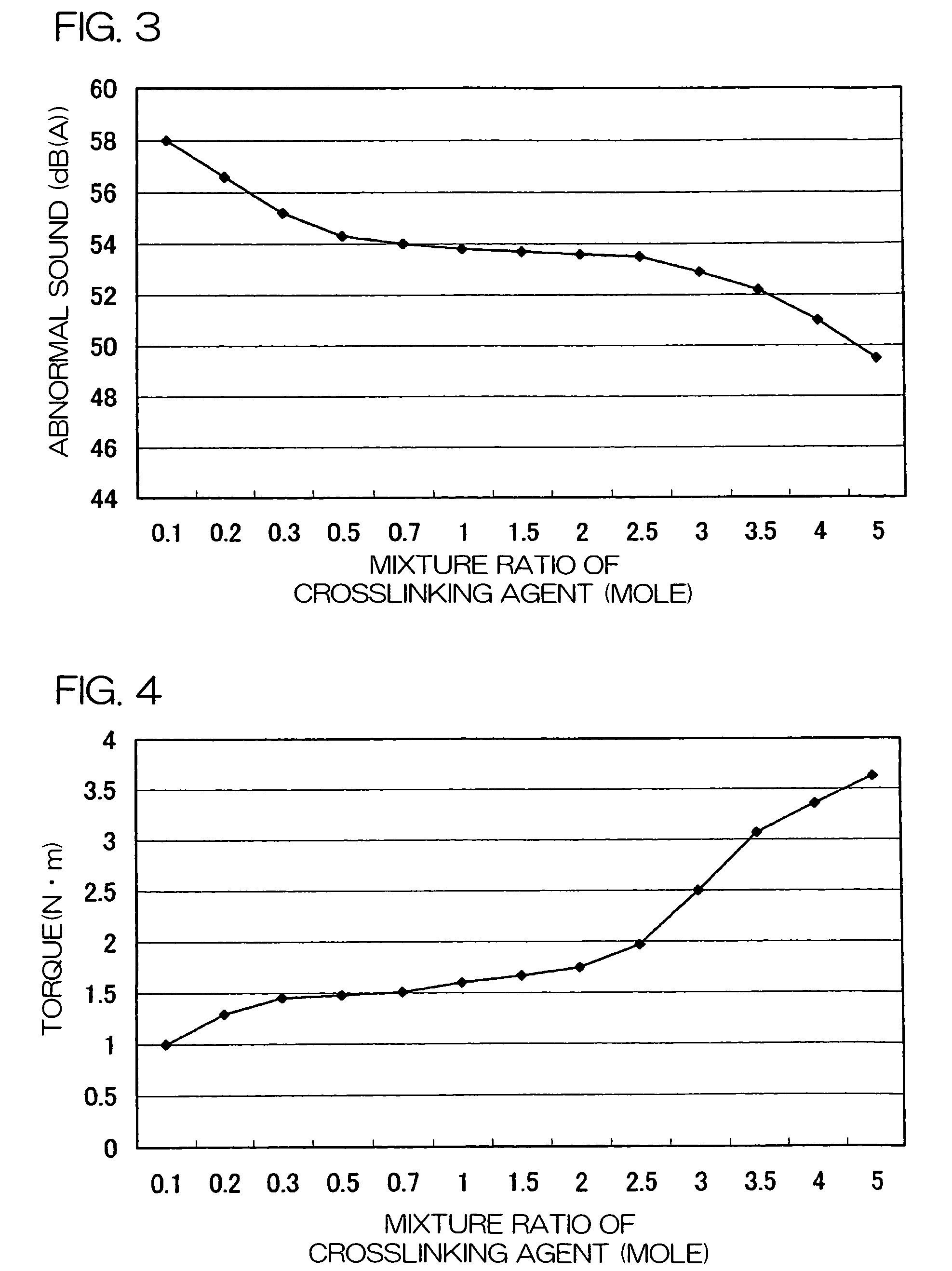
[0103]600 g of polyurethane resin particles serving as buffer particles having an average particle diameter of 150 μm and having a particle size distribution of 40 to 300 μm were produced in the same manner as that in the example 1-1 except that the respective mixture amounts of aliphatic polyester polyol A, aromatic polyester polyol B, and trimethylolpropane were adjusted so that the mixture amount of the trimethylolpropane per 1 mole of the total amount of the aliphatic polyester polyol A and the aromatic polyester polyol B was 0.1 to 5 moles, as shown in Table 1, described later, and the concentration of an isocyanate end group was adjusted, while maintaining 50 / 50 as the weight ratio A / B of the aliphatic polyester polyol A to the aromatic polyester polyol B.

(Production and Evaluation of Lubricant Composition)

[0104]The polyurethane resin particles produced in the above-mentioned examples 1-1˜1-13 were mixed at a mixture ratio of 40 parts by weight to 100 parts by ...

example 2-1

[0108]Used as aliphatic polyester polyol A and aromatic polyester polyol B were respectively the same ones as those used in the example 1-1.

[0109]346.8 g of the aliphatic polyester polyol, 61.2 g of the aromatic polyester polyol, 490 g of isooctane serving as a dispersion medium, and 37 g of a dispersion stabilizer [N-5741 manufactured by NIPPON POLYURETHANE INDUSTRY CO., LTD.] were fed into a 1 liter flask while supplying nitrogen to the flask. The weight ratio of the aliphatic polyester polyol A to the aromatic polyester polyol B was set to A / B=85 / 15.

[0110]Agitation was then started. 0.003 g of di-n-butyltin dilaurate serving as a catalyst was added with the aliphatic polyester polyol and the aromatic polyester polyol dispersed in isooctane, and 138 g of hexamethylene diisocyanate serving as polyisocyanate was further added, followed by reaction at 80 to 90° C. for three hours.

[0111]At the time point where the concentration of an isocyanate end group reached 4.6% upon sequentially...


PUM

PropertyMeasurementUnit
particle diameter D1aaaaaaaaaa
average particle diameter D1aaaaaaaaaa
particle diameteraaaaaaaaaa

Abstract

Disclosed are a lubricant composition to which is added as buffer particles to a lubricant polyurethane resin particles obtained by reacting and synthesizing long-chain polyol having a number-average molecular weight of not less than 500, a crosslinking agent having three or more active hydrogen groups in one molecule, and polyisocyanate as buffer particles, a speed reduction gear filled with the lubricant composition, and an electric power steering apparatus having the speed reduction gear incorporated therein, wherein noise produced by the speed reduction gear can be made lower than ever before irrespective of the magnitude of backlash in a case where a worm and a worm wheel are combined with each other and without complicating the configuration of the speed reduction gear by the buffer action of the buffer particles added to the lubricant composition, thereby making it possible to reduce noise produced in an automobile due to the electric power steering apparatus at low cost.

Description

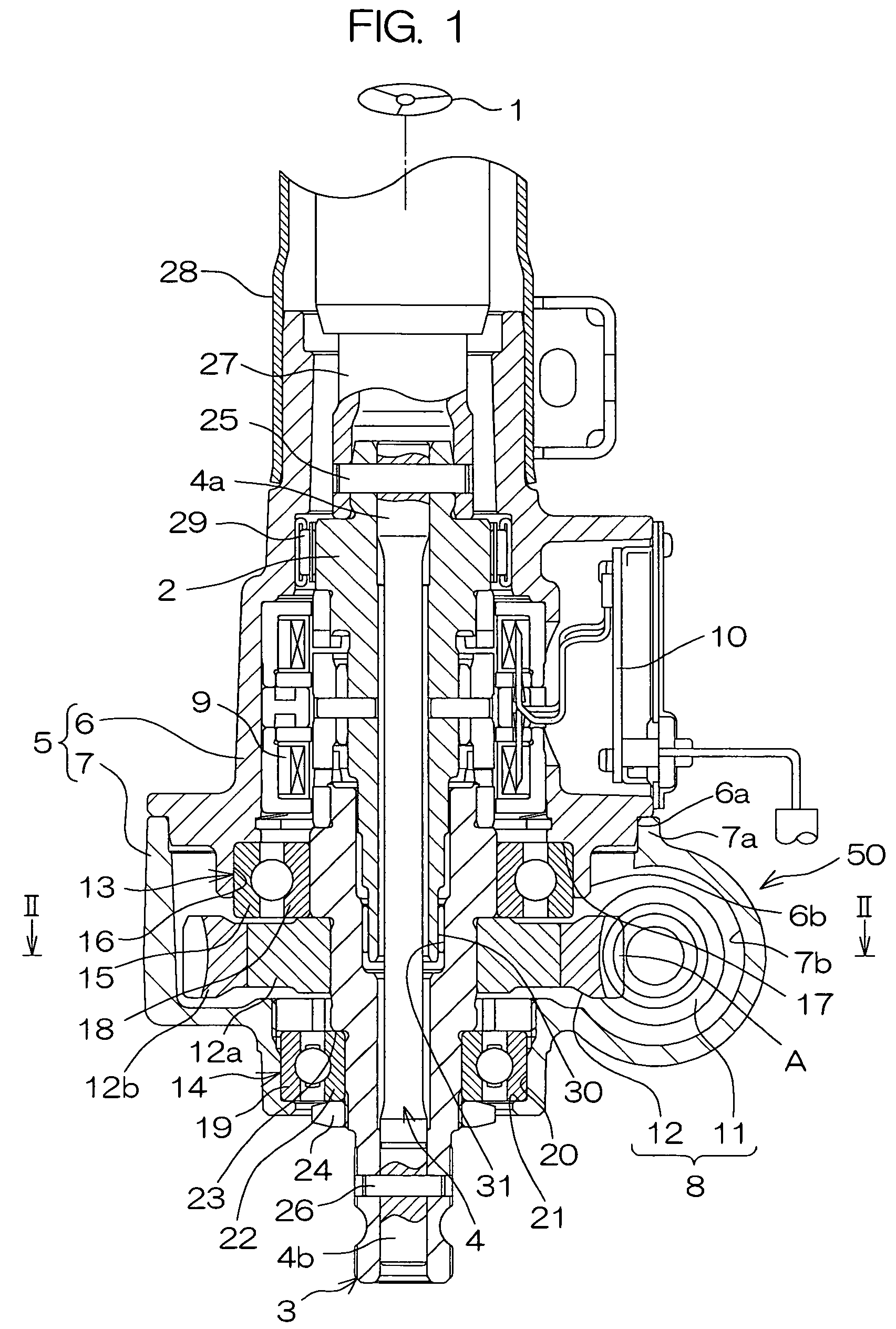
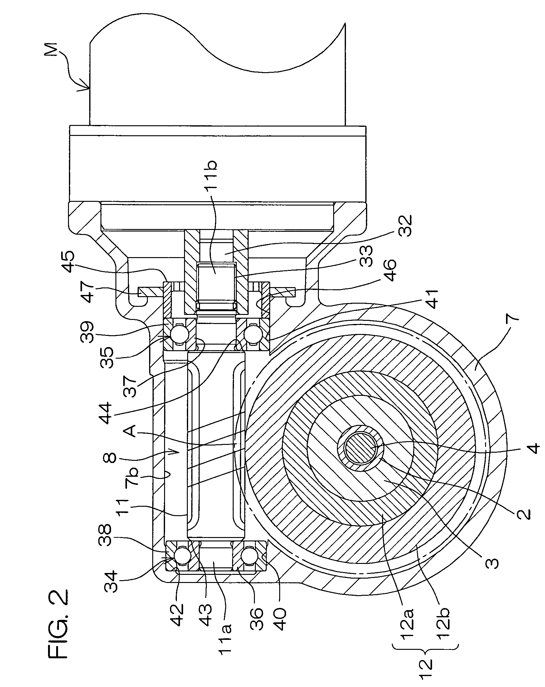
BACKGROUND OF THE INVENTION[0001]The present invention relates to a lubricant composition that can be suitably used for a speed reduction gear having a small gear such as a worm and a large gear such as a worm wheel, a speed reduction gear filled with the lubricant composition, and an electric power steering apparatus comprising the speed reduction gear.[0002]Speed reduction gears are used for electric power steering apparatuses for automobiles. In a column type EPS (Electric Power Steering System), for example, the rotation of an electric motor is transmitted from a small gear such as a worm to a large gear such as a worm wheel in a speed reduction gear to reduce its speed as well as to amplify its output, and is then provided to a column, thereby torque-assisting a steering operation.[0003]Suitable backlash is required to engage the small and large gears which serve as a speed reduction mechanism. At the time of forward / backward rotation of the gears and in a case where an automob...

Claims


Application Information

Patent Timeline
Patent Type & Authority Patents(United States)
IPC IPC(8): C10M149/20B62D5/04C10M149/00C10M149/12C10M169/00C10M169/02C10N20/00C10N20/02C10N20/06C10N30/00C10N40/04C10N50/10F16H57/04
CPCB62D5/0409C10M149/00C10M149/20C10M169/00C10M2205/0285C10M2217/04F16H57/0498C10N2220/08C10N2220/082C10N2230/00C10N2240/04C10N2250/10C10N2250/12C10N2220/021C10N2020/04C10N2020/06C10N2030/00C10N2040/04C10N2050/10C10N2020/055C10N2050/015A01G33/00E02B3/123E02B3/129
Inventor KITAHATA, KOUJIUCHIDA, NAOKIYONEDA, MITSUOHAYASHI, MASAHIRO
Owner NIPPON POLYURETHANE IND CO LTD
Learn More