Steam trap with capillary action based blocking arrangement

a technology of capillary action and blockage arrangement, applied in the field of steam traps, can solve the problems of present flow impediments and other inefficiencies, accumulation at low spots, and only suitable known steam traps

Inactive Publication Date: 2009-02-19
CHIANG YING CHUAN
View PDF17 Cites 10 Cited by
  • Summary
  • Abstract
  • Description
  • Claims
  • Application Information

AI Technical Summary

Benefits of technology

[0009]It is therefore one object of the invention to provide a steam trap for removing condensed water from a steam pipe having an end to which the strap is connected, comprising a hollow body having an inlet adapted to secure to the pipe end and an outlet, the body comprising a staged internal space; one or more blocking members secured in t

Problems solved by technology

And if, for example, the condensate is not removed, it will accumulate at low spots and present flow impediments and other inef

Method used


Image

  • Steam trap with capillary action based blocking arrangement
  • Steam trap with capillary action based blocking arrangement
  • Steam trap with capillary action based blocking arrangement

Examples


Embodiment Construction

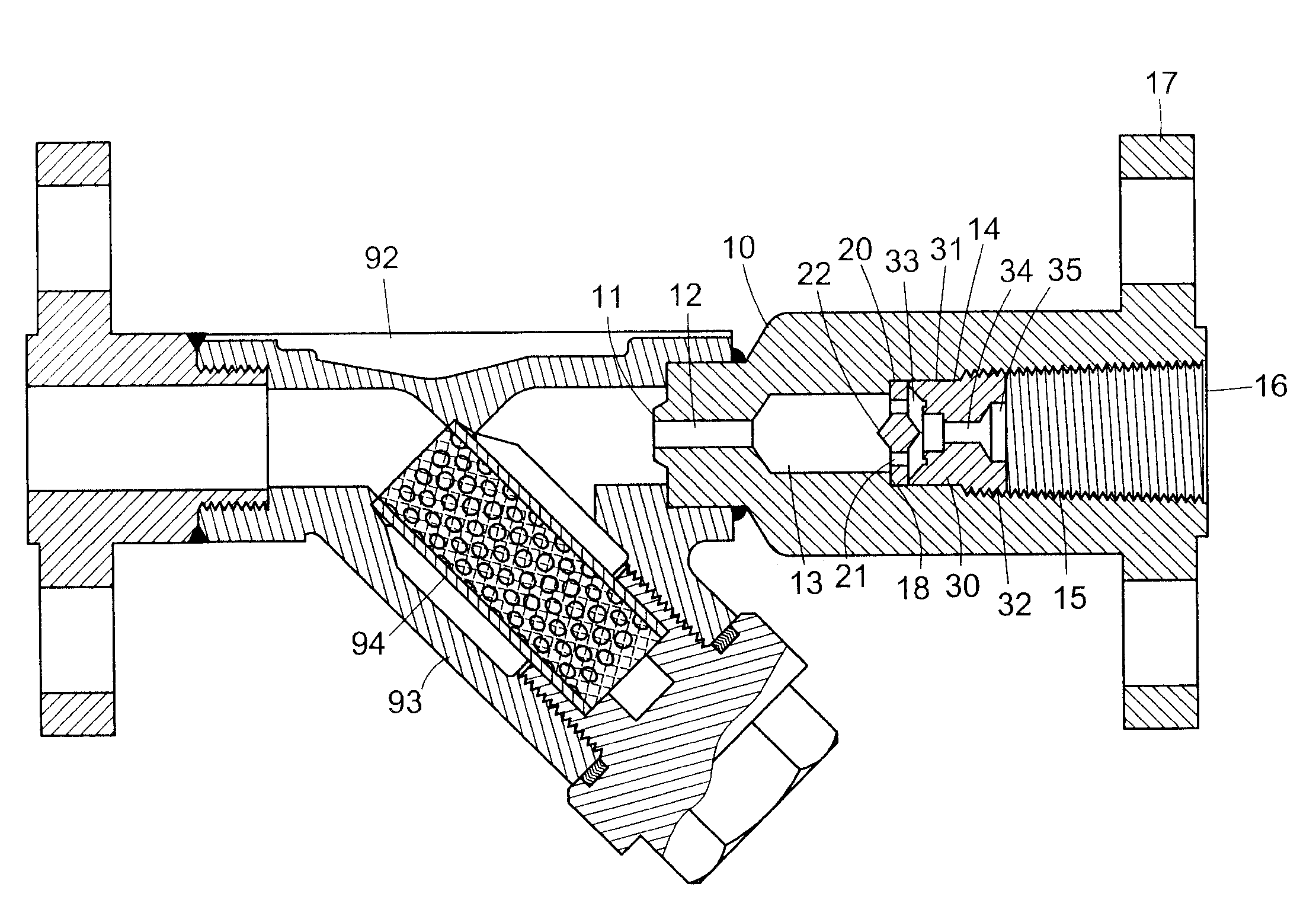
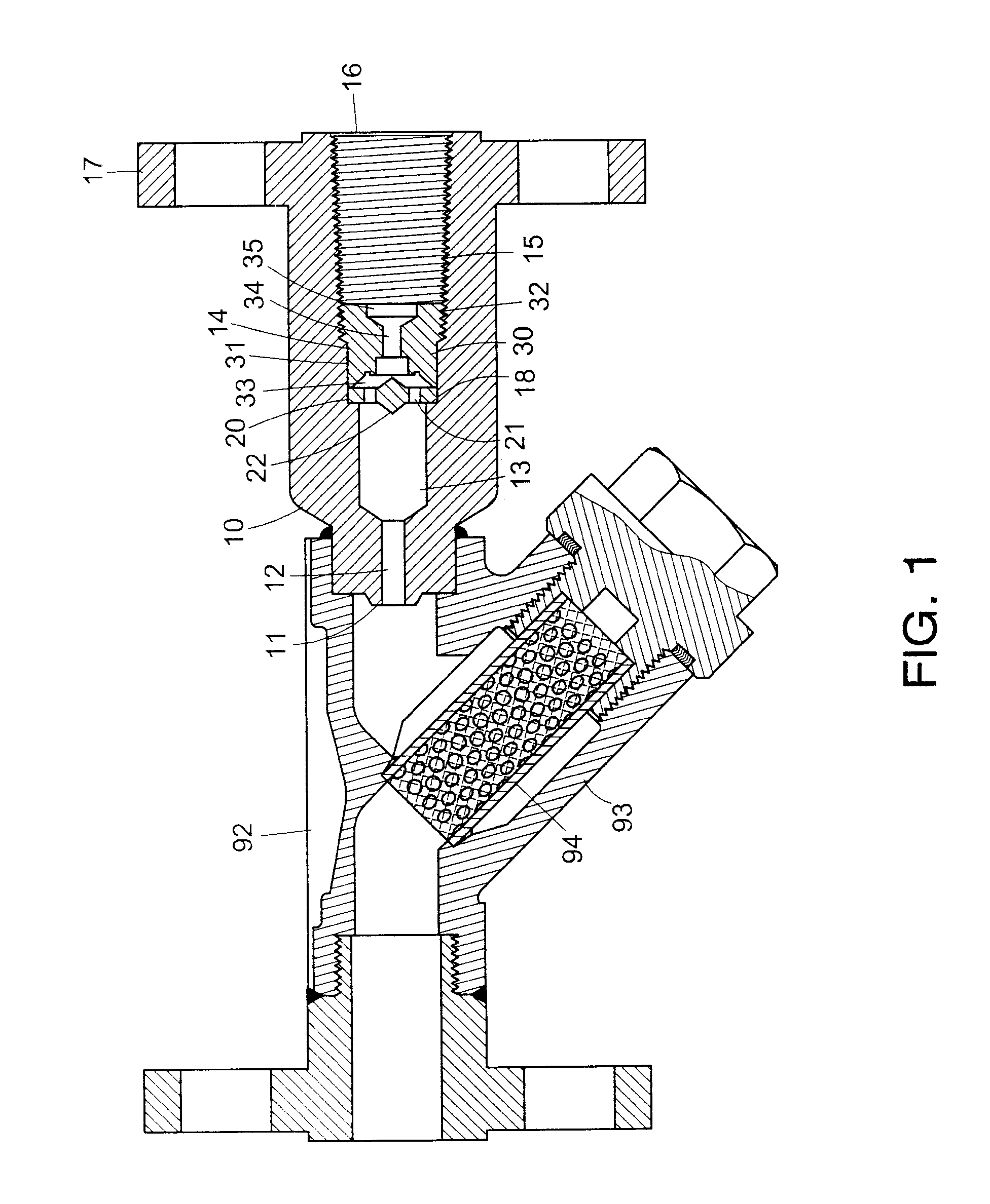
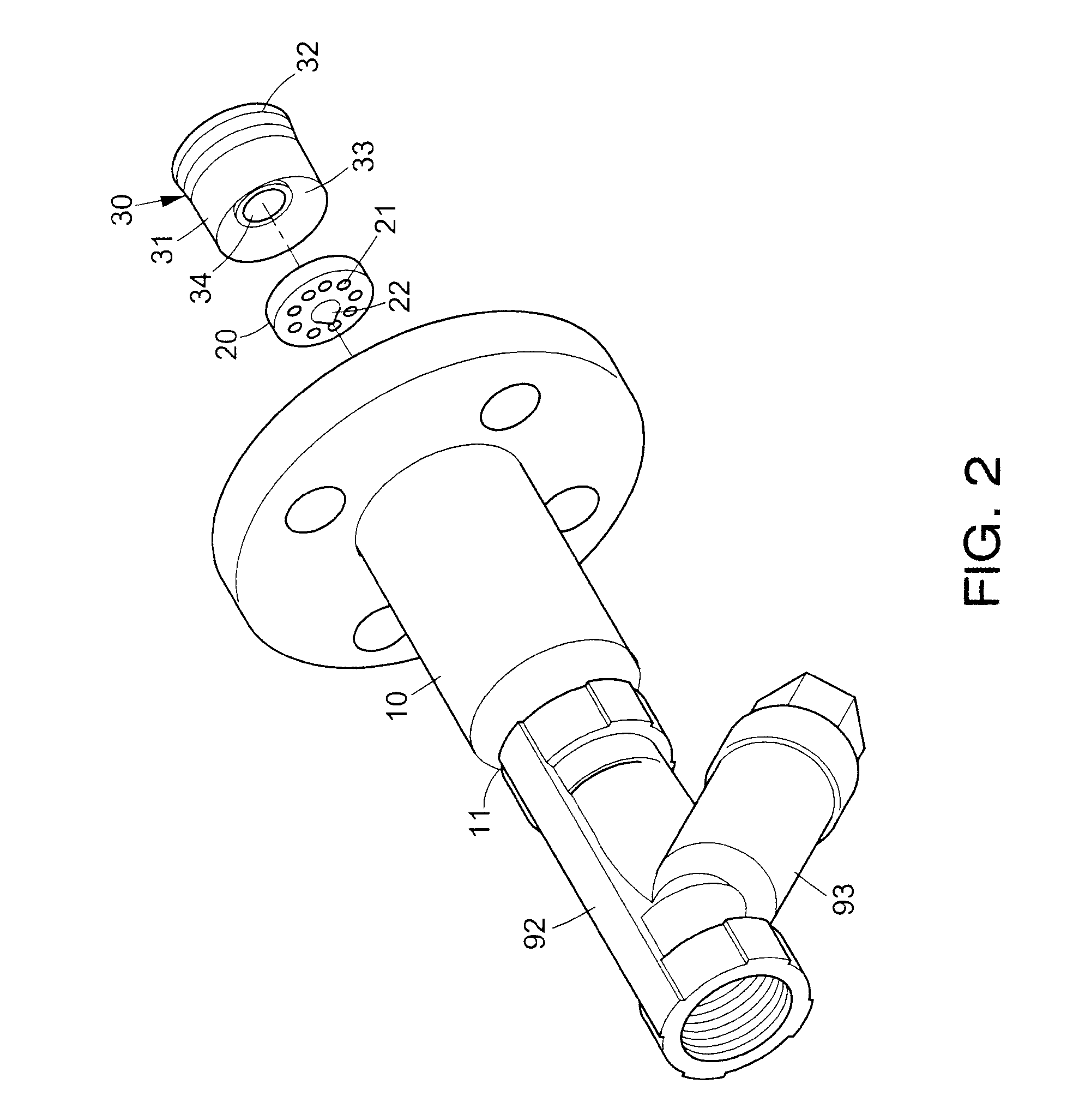
[0015]Referring to FIGS. 1 and 2, a steam trap in accordance with a first preferred embodiment of the invention comprises a cylindrical housing 10, a blocking member 20 in the housing 10, and an abutment member 30 in the housing 10. Each component is discussed in detail below.

[0016]Inner space of the housing 10 has a staged cross-section and is increased in size from a front position adjacent an inlet 11 to an outlet 16. An annular flange 17 is formed around the outlet 16 and is adapted to secure to a drain (not shown). The inner space of the housing 10 is provided with a first space 13 adjacent the inlet 11, and an enlarged second space 14 terminated at the outlet 16. A narrow fluid path 12 is formed in communication with the inlet 11 and the first space 13 at its both ends. A shoulder 18 is formed between the first and second spaces 13 and 14. Inner threads 15 are formed on a portion of the second space 14 terminating at the outlet 16.

[0017]A prior Y-strainer fitting 92 is provide...


PUM


Abstract

A steam trap is provided to remove condensed water from a steam pipe having an end to which the strap is connected. In one embodiment, the trap includes a hollow body having an inlet adapted to secure to the pipe end and an outlet, the body comprising a staged internal space; a blocking member secured in the space and comprising a central projection on either surface and a plurality of apertures around the projections; and an abutment member in the rear of the blocking member. Condensate is adapted to pass the apertures while the steam is substantially blocked by the apertures due to capillary action.

Description

BACKGROUND OF THE INVENTION[0001]1. Field of Invention[0002]The invention relates to pipe fitting and more particularly to a steam trap having one or more blocking members which are adapted to block steam from passing a drain path due to capillary action.[0003]2. Description of Related Art[0004]Conventionally, steam traps are used to remove water and gases from a steam line while preventing the escape of live steam. And if, for example, the condensate is not removed, it will accumulate at low spots and present flow impediments and other inefficiencies.[0005]A conventional orifice-type steam trap is shown in FIG. 4 and comprises a cylindrical housing 80 having an inlet 81 at one end and an outlet 82 at the other end. Within the housing 80 there are provided a narrow fluid path 83, an enlarged first space 84 adjacent the inlet 81, and an enlarged second space 85 adjacent the outlet 82. That is, the inner space of the housing 80 has a shoulder cross-section. Within the second space 85 ...

Claims


Application Information

Patent Timeline
IPC IPC(8): F16T1/16
CPCF16T1/38Y10T137/304
Inventor CHIANG, YING CHUAN
Owner CHIANG YING CHUAN
Why Eureka
Try Eureka