Optical scanning apparatus and image-forming apparatus

a scanning apparatus and image-forming technology, applied in the field of optical scanning apparatus and image-forming apparatus, can solve the problems of deterioration of formed images, deterioration of imaging performance, and and achieve the effect of correcting deterioration of imaging performan

Inactive Publication Date: 2009-02-19
CANON KK
View PDF43 Cites 0 Cited by
  • Summary
  • Abstract
  • Description
  • Claims
  • Application Information

AI Technical Summary

Benefits of technology

[0022]The present invention is directed to optical scanning apparatuses capable of correcting deterioration in imaging performance and curvature of a scanning line on a surface to be scanned and capable of forming high-definition and high-resolution images, and provides image-forming apparatuses using the same.

Problems solved by technology

However, when the inclination of the incoming beams and the scanning angle are increased as described above, the light beams obliquely incident on the deflection plane of the light deflector in the sub-scanning section draw a conical plane due to the deflection scanning of the light deflector (conical scan), resulting in the following two major problems.
A first problem is that the light beams obliquely incident on the deflection plane of the light deflector in the sub-scanning section draw a conical plane due to the deflection scanning of the light deflector, and thus, the curved scanning beams are incident on an fθ lens (imaging lens) disposed in the center of the oblique incoming beams such that a curved scanning line also appears on the surface of the photosensitive drum serving as the surface to be scanned.
This is the problem of the curvature of the scanning line caused by the incoming beams obliquely incident on the deflection plane of the light deflector in the sub-scanning section.
A second problem is deterioration in imaging performance since the scanning beams that are deflected from the deflection plane and reach the surface to be scanned draw a conical plane.
This is the problem of the deterioration in the imaging performance caused by the scanning beams drawing a conical plane.
When an optical scanning apparatus having the two problems described above is used for an image-forming apparatus, formed images are considerably deteriorated.
However, when the lens surfaces of the toric lens are formed such that the generatrices are curved in the sub-scanning direction, the shapes of the lens surfaces become complicated.
However, when the maximum scanning angle (maximum angle of view) or the inclination of the incoming beams incident on the deflection plane of the light deflector with respect to the deflection plane defined in the sub-scanning section is large in the imaging optical system, the deterioration in the imaging performance and the curvature of the scanning line on the surface to be scanned over the entire range of image heights are difficult to sufficiently regulate by changing the inclination of the toric lens in the sub-scanning section.

Method used


Image

  • Optical scanning apparatus and image-forming apparatus
  • Optical scanning apparatus and image-forming apparatus
  • Optical scanning apparatus and image-forming apparatus

Examples


first exemplary embodiment

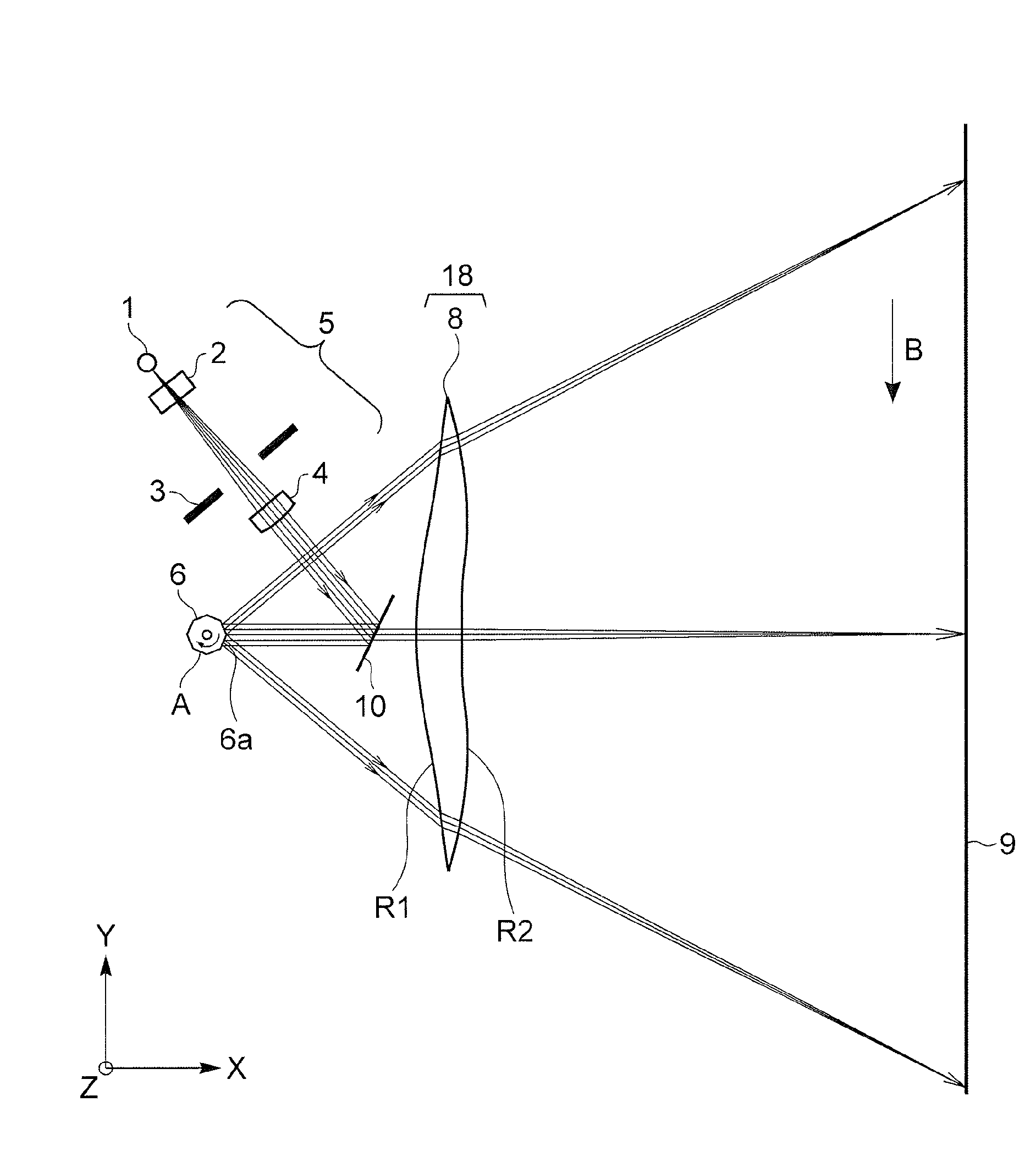
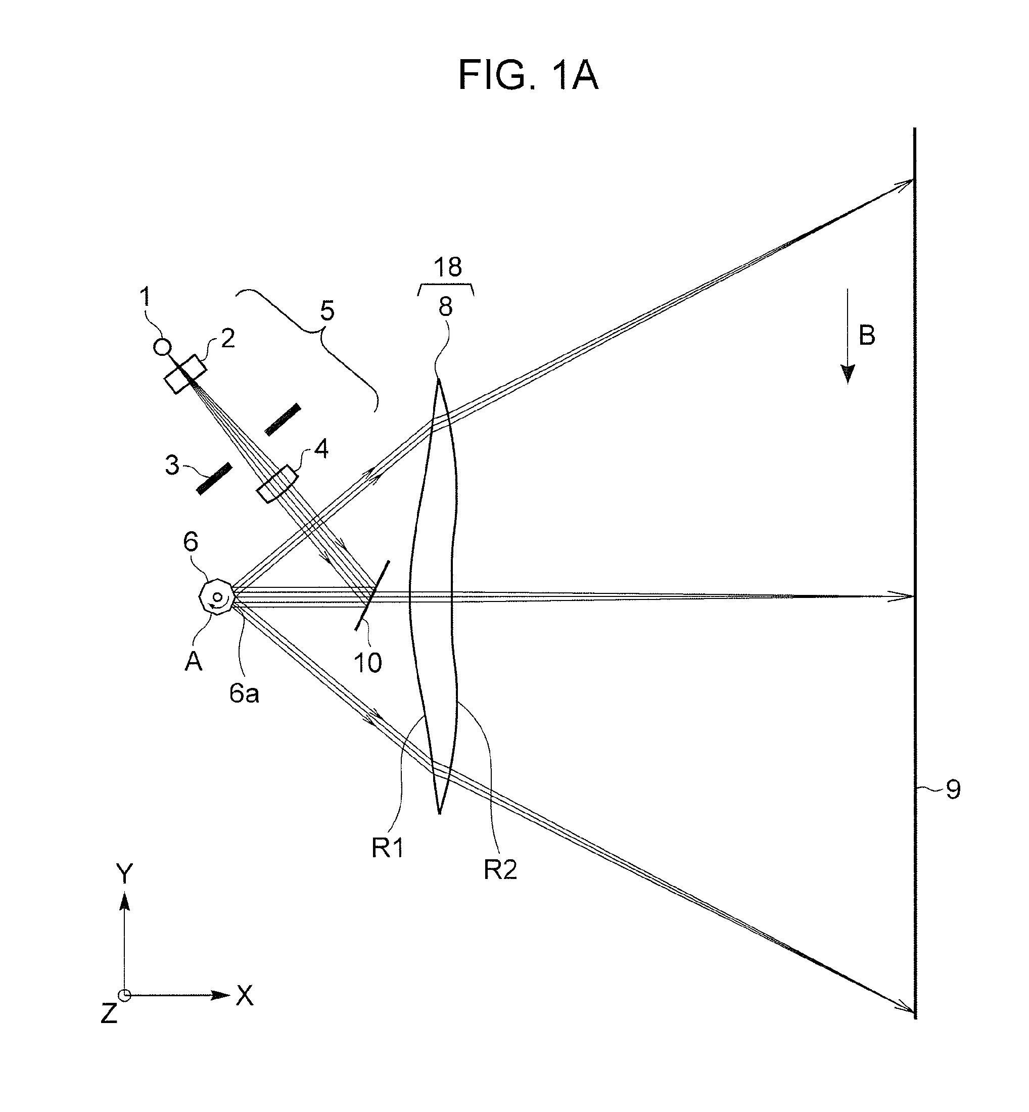
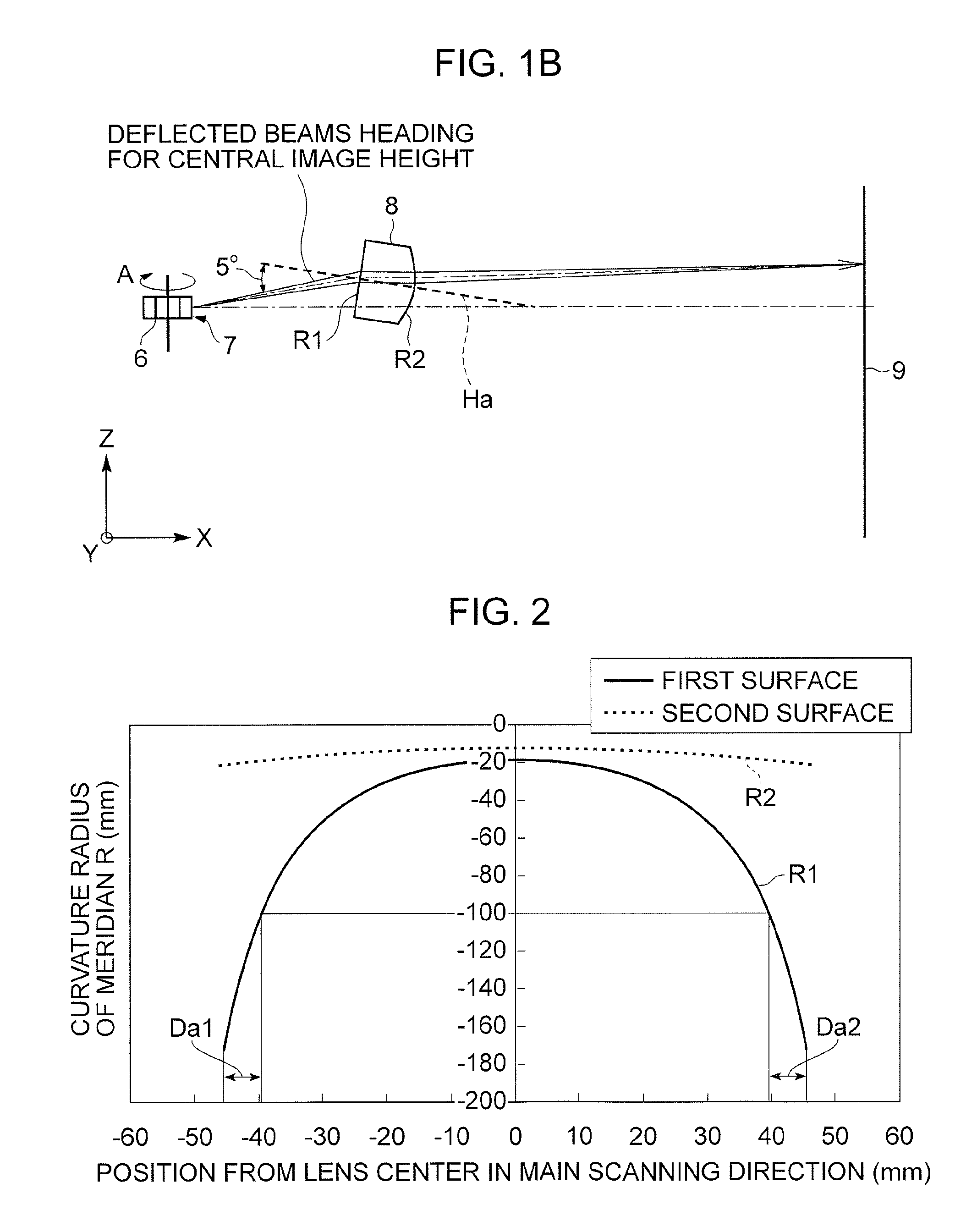
[0053]FIG. 1A is a cross-sectional view of principal parts in the main scanning direction (main scanning section) according to a first exemplary embodiment of the present invention, and FIG. 1B is a cross-sectional view of the principal parts in the sub-scanning direction (sub-scanning section) according to the first exemplary embodiment of the present invention.

[0054]Herein, the main scanning direction is a direction perpendicular to the rotation axis of a light deflector and the optical axis of an imaging optical system (the direction in which light beams are deflected by the light deflector). Herein, the sub-scanning direction is a direction parallel to the rotation axis of the light deflector. Moreover, the main scanning section is a plane parallel to the main scanning direction including the optical axis of the imaging optical system. Furthermore, the sub-scanning section is a section perpendicular to the main scanning section.

[0055]In the drawings, a light-source unit 1 can in...


PUM


Abstract

An optical scanning apparatus includes a light-source unit, an incident optical system for directing light beams emitted from the light-source unit to a deflecting unit, and an imaging optical system for guiding the light beams deflected from the deflecting unit to a surface to be scanned. The imaging optical system includes a toric lens whose power in the main scanning direction is different from that in the sub-scanning direction; the toric lens having the curvature centers of the meridians of a first toric surface connected to form a curved line located in a common plane Ha, and the curvature centers of the meridians of a second toric surface connected to form a curved line not located in a common plane.

Description

CROSS-REFERENCE TO RELATED APPLICATIONS[0001]This application is a continuation of U.S. patent application Ser. No. 11 / 432,211 filed May 10, 2006, which claims priority to Japanese Patent Application No. 2005-153931-filed May 26, 2005, both of which are hereby incorporated by reference herein in their entirety.BACKGROUND OF THE INVENTION[0002]1. Field of the Invention[0003]The present invention relates to an optical scanning apparatus and an image-forming apparatus using the same.[0004]2. Description of the Related Art[0005]To date, in an optical scanning apparatus, light beams modulated and emitted from a light-source unit are periodically deflected by a light deflector according to image signals, and converged on a plane of a photosensitive recording medium as a spot by an imaging optical system having an fθ characteristic such that images are recorded on the plane.[0006]Recently, such imaging optical systems have been required to be faster and more compact as apparatuses such as ...

Claims


Application Information

Patent Timeline
Patent Type & Authority Applications(United States)
IPC IPC(8): G02B26/10
CPCG02B26/125G02B26/10
Inventor TOMIOKA, YUICHI
Owner CANON KK
Why Eureka
Try Eureka