Apparatus for determining deterioration of photocoupler

a technology of photocoupler and apparatus, applied in the direction of electrical testing, measurement devices, instruments, etc., can solve the problem of unavoidable increase in circuit size, and achieve the effect of suppressing the increase in circuit siz

Active Publication Date: 2019-07-30
DENSO WAVE INC
View PDF7 Cites 0 Cited by
  • Summary
  • Abstract
  • Description
  • Claims
  • Application Information

AI Technical Summary

Benefits of technology

[0007]Accordingly it is desired to suppress increase in circuit size in an apparatus that determines the deterioration of a photocoupler to which a predetermined alternating-current voltage is applied.
[0016]In this regard, in the above-described configuration, the photocoupler is determined to have deteriorated when the amount by which the low-pass filtered pulse signal exceeds a threshold is less than a predetermined amount. Therefore, the deterioration of the photocoupler can be accurately determined even when the pulse signal has been passed through a low-pass filter.
[0017]Specifically, a configuration can be used in which, when the amount by which the low-pass filtered pulse signal exceeds the threshold is zero, or in other words, when the pulse signal that has passed through the low-pass filter does not exceed the threshold, the photocoupler is determined to have deteriorated. In a configuration such as this, the deterioration of the photocoupler can be easily determined.

Problems solved by technology

Therefore, increase in circuit size is unavoidable.

Method used


Image

  • Apparatus for determining deterioration of photocoupler
  • Apparatus for determining deterioration of photocoupler
  • Apparatus for determining deterioration of photocoupler

Examples


first embodiment

[0028](First Embodiment)

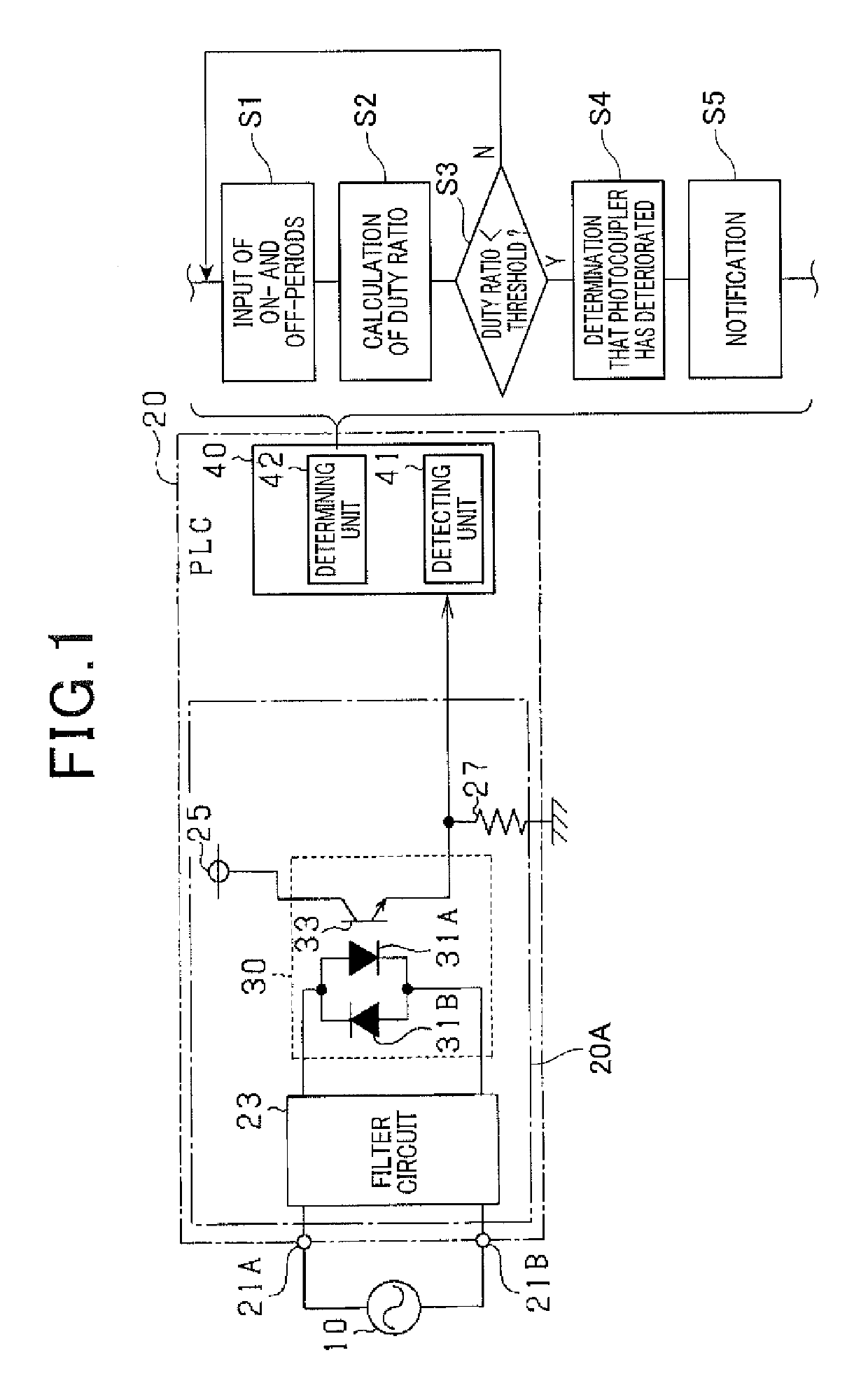
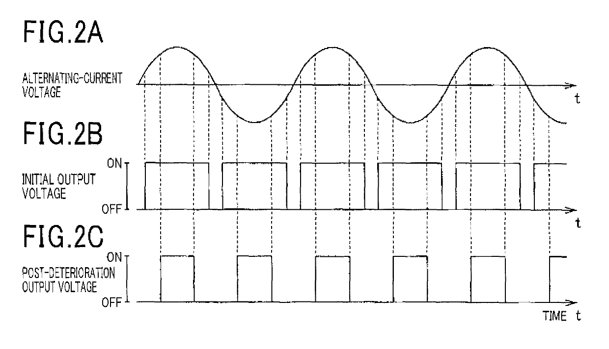
[0029]Referring to FIGS. 1 and 2, an apparatus for determining deterioration of a photocoupler, which is called simply a “deterioration determining apparatus,” will now be described. In the first embodiment, this deterioration determining apparatus is integrally incorporated in a programmable logic controller (PLC). The PLC is provided therein with an alternating-current voltage input circuit to which an alternating-current (Ac) voltage is applied.

[0030]As shown in FIG. 1, a PLC 20 includes an alternating-current voltage input circuit 20A to which an AC voltage is applied and a processor 40 which is produced as an application-specific integrated circuit (ASIC).

[0031]The alternating-current voltage input circuit 20A includes input terminals 21A and 21B, a filter circuit 23 for noise reduction, a photocoupler 30, a direct-current power supply 25, and a resistor 27. The input terminals 21A and 21B are connected to an alternating-current power supply 10. The alte...

second embodiment

[0053](Second Embodiment)

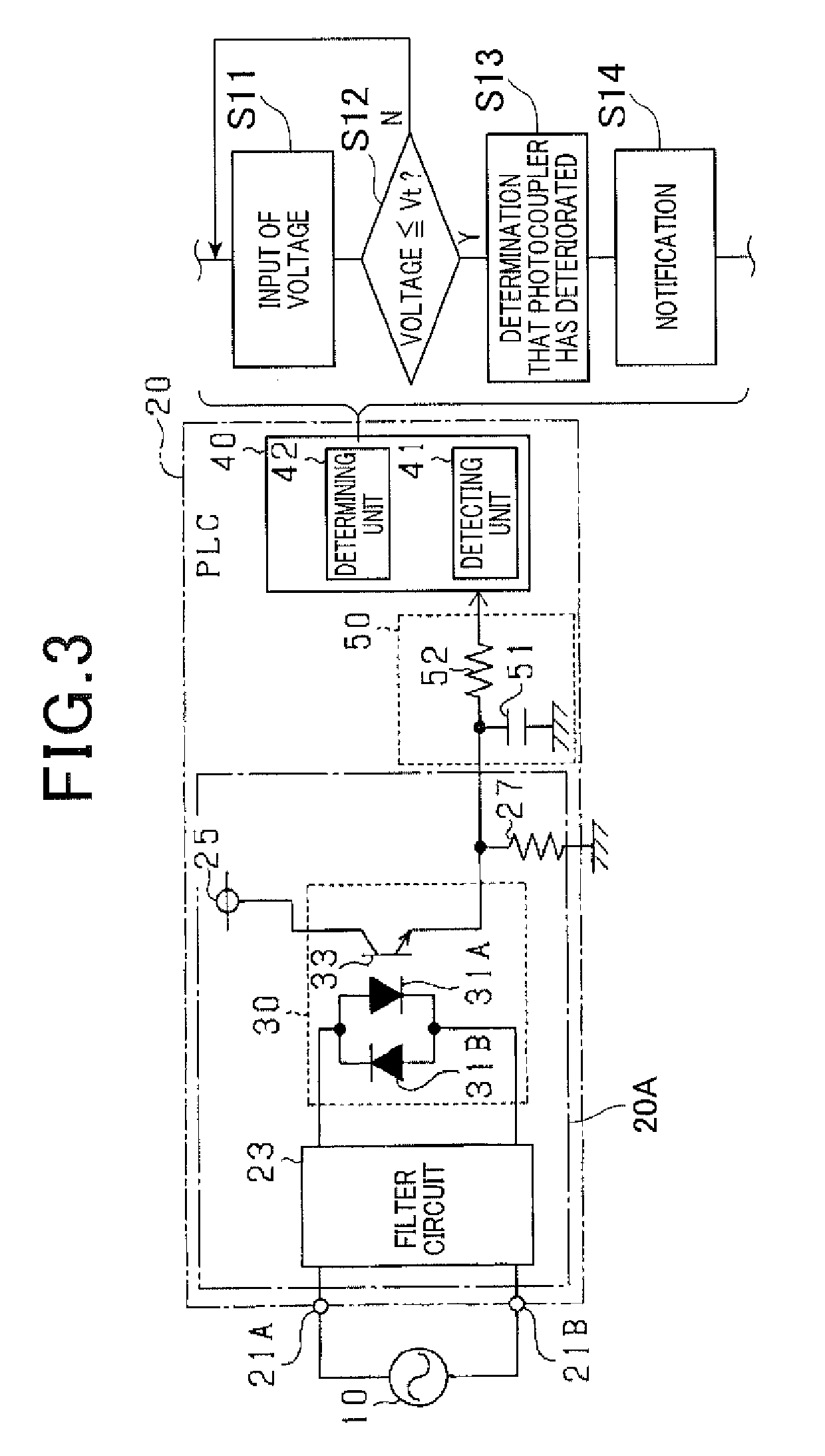
[0054]Referring to FIGS. 3 and 4, a second embodiment of the determination apparatus will now be described with reference to the drawings.

[0055]According to the present embodiment, as shown in FIG. 3, the pulse signal outputted by the photocoupler 30 is inputted to the processor 40 after passing through a low-pass filter 50. The points that differ from the first embodiment will now mainly be described hereafter. Components that are the same as those according to the first embodiment are given the same reference numbers. Therefore, descriptions thereof are omitted.

[0056]The output terminal of the photocoupler 30 is connected to the input terminal of the low-pass filter 50. The output terminal of the low-pass filter 50 is connected to the input terminal of the processor 40. In other words, the pulse signal outputted by the photocoupler 30 is inputted to the processor 40 via the low-pass filter 50.

[0057]In the present embodiment, the deterioration determining a...


PUM


Abstract

An apparatus is provided to determine deterioration of a photocoupler. The apparatus includes a detecting unit and a determining unit. The detecting unit receives an electric pulse signal outputted from the photocoupler. The amplitude of the outputted pulse signal depends on that of an electric AC voltage applied to the photocoupler. The detecting unit detects a duty ratio of the pulse signal. The determining unit determines whether or not the duty ratio is less than a threshold given for the determination. The determining unit also determines that the photocoupler has deteriorated in performance thereof more than a usable level if it is determined that the duty ratio is less than the threshold given for the determination.

Description

CROSS-REFERENCE TO RELATED APPLICATION[0001]This application is based on and claims the benefit of priority from earlier Japanese Patent Application No. 2014-018682 filed on Feb. 3, 2014 the descriptions of which are incorporated herein by reference.BACKGROUND OF THE INVENTION[0002][Field of the Invention][0003]The present invention relates to an apparatus that detects the deterioration of a photocoupler to which a predetermined alternating-current (AC) voltage is applied.[0004][Description of the Related Art][0005]Conventionally, there is a technology in which the output voltage of a photocoupler, to which a predetermined direct-current voltage is applied, is compared to a reference voltage by a comparator. The photocoupler is determined to have deteriorated when the output voltage of the photocoupler is lower than the reference voltage (refer to JP-A-2009-71928).[0006]The technology described in JP-A-2009-71928 requires the addition of a power supply that generates the reference v...

Claims


Application Information

Patent Timeline
Patent Type & Authority Patents(United States)
IPC IPC(8): G01R31/26
CPCG01R31/2637G01R31/2635
Inventor SUMIYOSHI, YOKO
Owner DENSO WAVE INC
Why Eureka
Try Eureka