Time-temperature indicators

a technology of time-temperature indicators and indicators, applied in the field of temperature indicators, can solve the problems of not providing further information on the thermal history of the product, and the useful life span of products generally is limited and may be significantly shortened

Inactive Publication Date: 2009-02-26
AUSTRALIEN NAT UNIV
View PDF11 Cites 15 Cited by
  • Summary
  • Abstract
  • Description
  • Claims
  • Application Information

AI Technical Summary

Benefits of technology

[0011]In an embodiment of the invention there is provided a visual thermal history indicator comprising a pattern produced from at least two waxes wherein one wax has a melting point that differs from the other wax, or where the waxes have the same melting point but different melt flow behaviour, and wherein the pattern is adapted s

Problems solved by technology

These products generally have limited useful life spans that may be significantly shortened by exposure to relatively high temperatures for a specific time period during storage, distribution, or use.
A limitation of the indicators of the invention of this citation is that

Method used


Image

  • Time-temperature indicators
  • Time-temperature indicators
  • Time-temperature indicators

Examples


example 1

Wax Compositions

[0065]Wax compositions were prepared and tested by combining solid paraffin wax obtained from Walker Ceramics, Victoria Australia, (product number BA693); liquid paraffin wax obtained from Fluka, (product Number 76233) CAS [8002-72-2] and commercially available candle wax dyes.

[0066]The melting point of the solid paraffin wax was determined to be 58-62° C.

[0067]Mixtures of the waxes and dye were combined and mixed together at a temperature above the melting point of the highest component and allowed to solidify before the approximate melting point was determined. The dye comprised 0.5-1.0 wt % of the mixture. The approximate melting point was determined visually by using an oven and the results are set out in Table 1 below.

TABLE 1Wax compositions and approximate melting pointsWt % solid waxWt % liquid waxMelting point ° C.Notes158531colourless208039colourless257540Blue dye336744Green dye485245Yellow dye505048colourless802053Red Dye

[0068]The above results demonstrated...

example 2

Dye Combinations

[0070]Assorted candle dyes were used to colour the paraffin wax. The colours used were red, yellow and blue. It was observed that the melting point of a wax composition containing 0.5-1.0 wt % candle dye is ˜1-3° C., higher than the wax composition without the dye. It is believed that this merely reflects the higher melting point of the wax base of the dye materials.

[0071]Mixtures of the dyes were added to the wax composition and it was observed that the mixture of coloured dyes could be used to provide a wide range of different colours. Red dye and yellow dye provided an orange coloured wax composition. Likewise, blue dye and red dye gave a purple coloured wax composition and blue and yellow gave green coloured wax composition.

example 3

Visual Thermal History Indicator

[0072]A series of experiments were conducted to investigate the behaviour of the waxes when heated above their melting temperature.

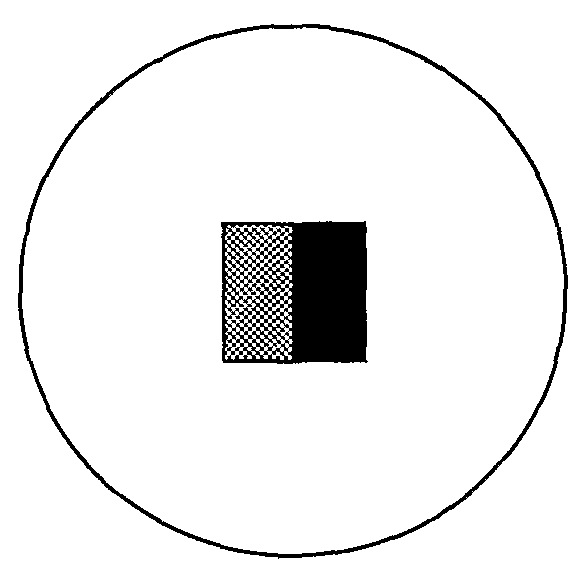
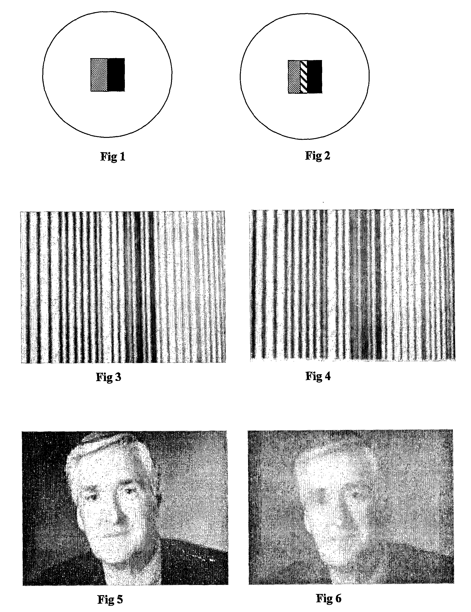
[0073]With reference to FIG. 1, a strip of yellow coloured wax (shown in hash) and blue wax (shown in solid black) were placed in a glass Petrie dish of diameter 60 mm to depth of approximately 1 mm. The side edges of the two wax stripes were contact with each other. A molten colourless wax with a melting point higher than the two coloured waxes was added into the dish and surrounded coloured strips of wax and was allowed to cool and solidify before testing.

[0074]The dish and waxes were heated for one hour in an oven at a temperature above the melting point of the coloured waxes but below the melting point of the colourless wax and then allowed to cool.

[0075]The result of the heating is shown in FIG. 2. It was found that the original coloured waxes had mixed in a region near the area of contact of the two strips. This cent...


PUM


Abstract

A visual thermal history indicator comprising a pattern produced from at least two waxes wherein one wax has a melting point that differs from the other wax, or where the waxes have the same melting point but different melt flow behaviour, and wherein the pattern is adapted so that when the lower melting point wax melts or the wax with greater melt flow behaviour flows, the visual appearance of the pattern changes, and wherein when the second and subsequent higher melting waxes melt, or when the lower melt flow behaviour waxes flow, the visual appearance of the pattern changes as each wax melts or flows.

Description

FIELD OF THE INVENTION[0001]This invention relates to temperature indicators that may be applied directly or indirectly to packaging for perishable or heat sensitive products by deposition. The temperature indicators are formed from wax based inks and may also be applied directly or indirectly to products by deposition to provide information about the thermal history of the products.BACKGROUND OF THE INVENTION[0002]It is desirable to be able to provide an indication whether a product has been exposed to an undesirable time-temperature history. This applies to perishables such as foods and pharmaceuticals. These products generally have limited useful life spans that may be significantly shortened by exposure to relatively high temperatures for a specific time period during storage, distribution, or use.[0003]This also applies to when a predetermined time-temperature history may be required during processing or use of the product. It also pertains to certain products such as canned go...

Claims


Application Information

Patent Timeline
IPC IPC(8): G01K1/02G01K11/06
CPCG01K1/02G01N31/229G01K11/06G01K3/04
Inventor CRAIG, VINCENTSENDEN, TIMOTHY JOHNKUGGE, CHRISTIAN
Owner AUSTRALIEN NAT UNIV
Why Eureka
Try Eureka