
Structure Of Memory Stick

a technology of memory sticks and structures, applied in the direction of casings/cabinets/drawers, casings/cabinets/drawers details, electrical appliances, etc., can solve the problems of liquid leakage and damage to circuit boards, and achieve the effect of waterproof effect and higher assembly stability

Inactive Publication Date: 2009-02-26
LIU CHIN TONG
View PDF18 Cites 0 Cited by
  • Summary
  • Abstract
  • Description
  • Claims
  • Application Information

AI Technical Summary

Benefits of technology

[0005]The present invention has been made to overcome the above-mentioned drawback of conventional structure of flash memory stick. The primary object of the present invention is to provide a novel structure for flash memory stick with higher assembly stability and waterproof effect.
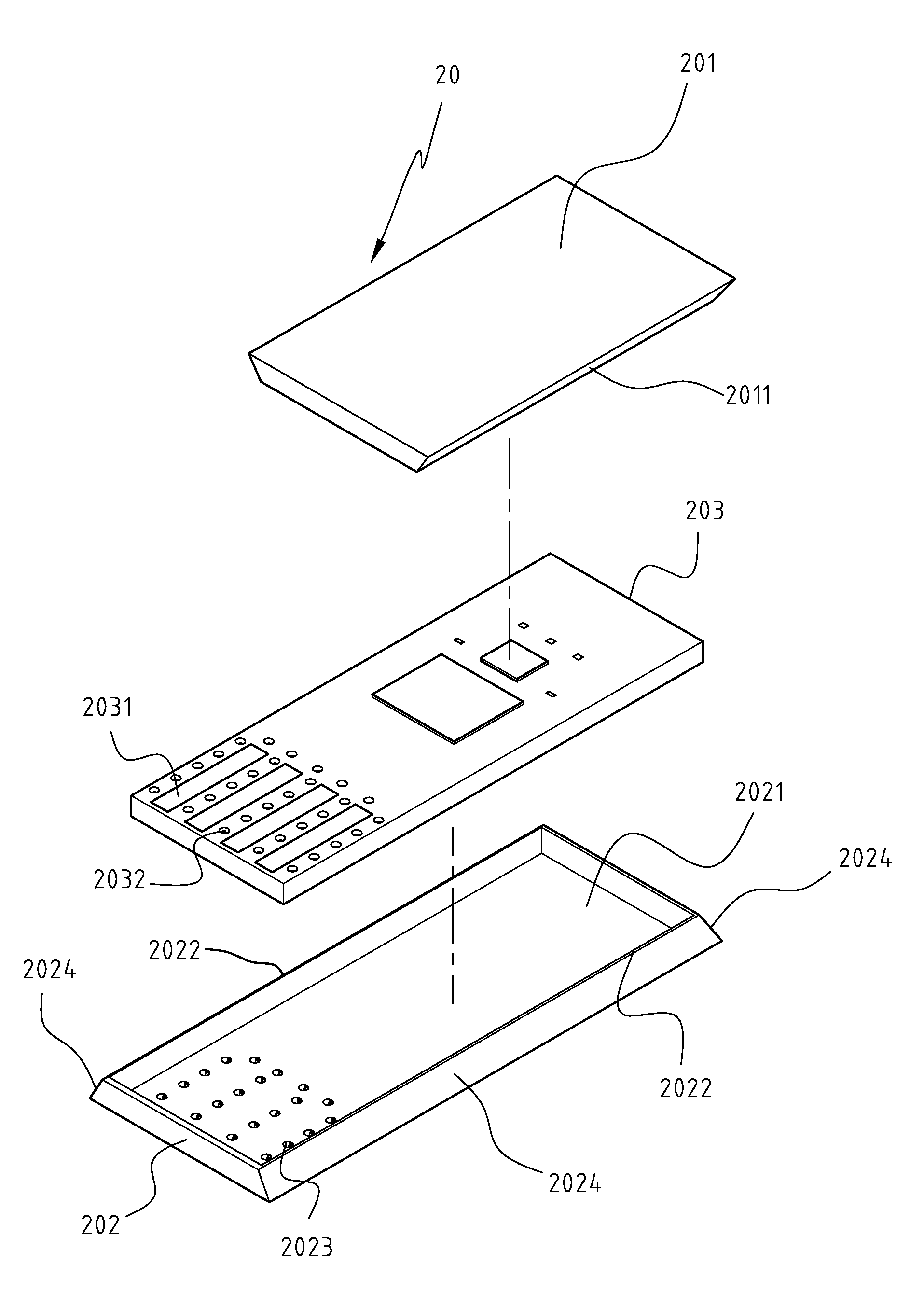
[0006]To achieve the above object, the present invention provides a structure of memory stick, including a substrate case, a bottom case, a circuit board and a cover layer, where the bottom of the bottom case forms a flat surface. The boundary of the flat surface forms a boundary stop wall. One end of the flat surface includes a plurality of concave trenches. The flat surface and the boundary stop wall from a housing space for the circuit board. One end of the circuit board includes a plurality of metal plates surrounded by a plurality of via holes. The via holes correspond to the concave trenches of the bottom case. The substrate case covers the top of circuit board and the bottom case. The cover layer is formed to cover the circumference of the engagement part of the substrate case and the bottom case, as well as the surrounding of the metal plates of the circuit board. The cover layer is formed by an inject molding process. During the injection molding process, the material of the cover layer also fills the via holes of the circuit board and the concave trenches of the bottom case so that the substrate case, bottom case, circuit board and cover layer all engage together so as to achieve the object of higher assembly stability and waterproof effect.

Problems solved by technology

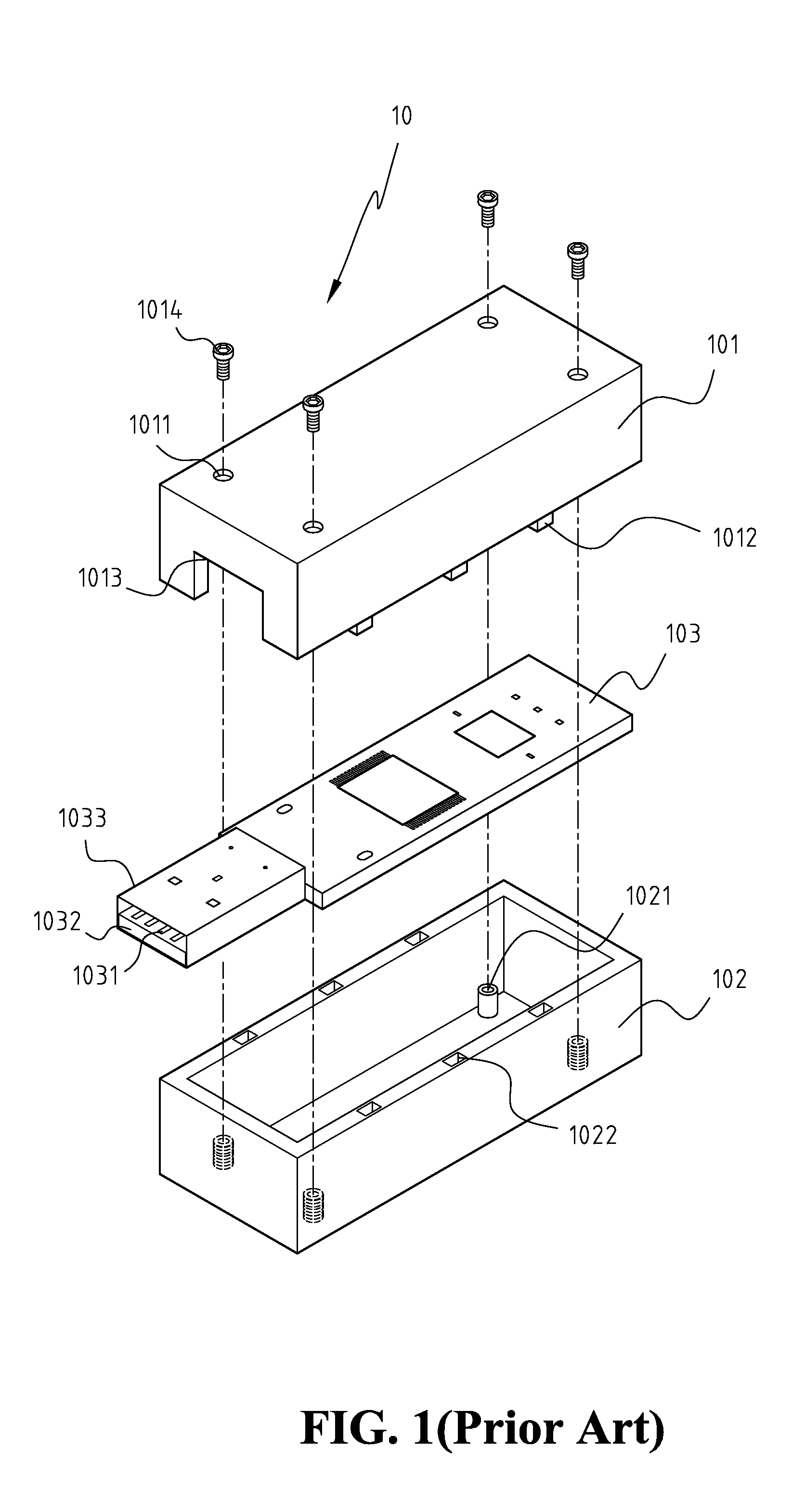
However, as screws 1014 of memory stick 10 may become loose after a long period of use and lead to the loose engagement of upper case 101 and lower case 102 so that liquid may leak in and damage circuit board 103.

Method used


Image

  • Structure Of Memory Stick
  • Structure Of Memory Stick
  • Structure Of Memory Stick

Examples


Embodiment Construction

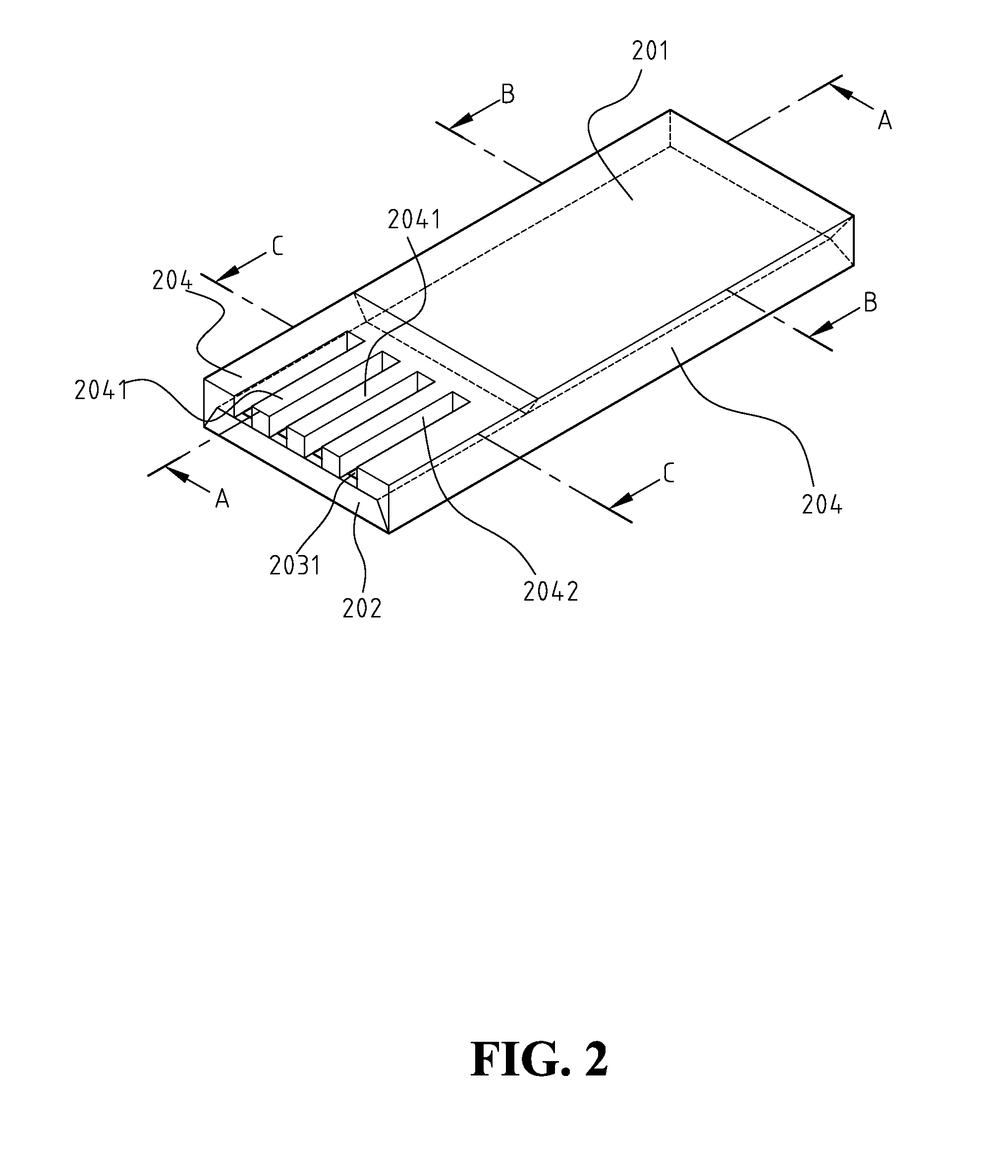
[0016]FIGS. 2 and 3 show a three-dimensional view and an dissected view of the memory stick of the present invention. The memory stick 20 of the present invention includes a substrate case 201, a bottom case 202, a circuit board 203 and a cover layer 204, where the bottom of bottom case 202 forms a flat surface 2021. The boundary of flat surface 2021 forms a boundary stop wall 2022. One end of flat surface 2021 includes a plurality of concave trenches 2023. Flat surface 2021 and boundary stop wall 2022 from a housing space for circuit board 203. At least two outer walls of boundary stop wall 2022 are slant surface 2024. In the present embodiment, three outer walls of boundary stop wall 2022 are slant surface 2024, with wide bottom and narrow top. One end of circuit board 203 includes a plurality of metal plates 2031 surrounded by a plurality of via holes 2032. Via holes 2032 correspond to concave trenches 2023 of bottom case 202. Circuit board 203 includes control chips, memory chip...


PUM


Abstract

A structure of memory stick is provided, including a substrate case, a bottom case, a circuit board and a cover layer. One end of the circuit board includes a plurality of metal plates surrounded by a plurality of via holes. The circuit board is placed inside the bottom case so that the via holes correspond to the concave trenches of the bottom case. The substrate case covers the top of circuit board with the metal plates exposed. The cover layer is formed to cover the circumference of the engagement part of the substrate case and the bottom case, as well as the surrounding of the metal plates of the circuit board. The cover layer is formed by an inject molding process so that the substrate case, bottom case, circuit board and cover layer all engage together so as to achieve the object of higher assembly stability and waterproof effect.

Description

FIELD OF THE INVENTION[0001]The present invention generally relates to a structure of memory sticks, and more specifically to a structure of memory sticks with better assembly stability and water-proof effects.BACKGROUND OF THE INVENTION[0002]FIG. 1 shows a schematic view of the components of a structure of a conventional memory stick. As shown in FIG. 1, memory stick 10 includes an upper case 101, a lower case 102 and a circuit board 103. The bottom of lower case 102 includes a plurality of screw holes 1021. A plurality of female buckle parts 1022 is formed on the top of circumference stop wall of lower case 102. The size of circuit board 103 is slightly smaller than the bottom surface of lower case 102, and circuit board 103 is placed inside lower case 102. One end of circuit board 103 extends a plurality of metal plates 1031 beyond the circumference stop wall of lower case 102. Metal plates 1031 are located on the surface of a fixed plate 1032. Fixed plate 1032 and metal plates 1...

Claims


Application Information

Patent Timeline
Patent Type & Authority Applications(United States)
IPC IPC(8): H05K5/02
CPCH05K5/0278
Inventor LIU, CHIN-TONG
Owner LIU CHIN TONG
Learn More