Directional backlight, display apparatus, and stereoscopic display apparatus

a stereoscopic display and backlight technology, applied in the direction of illuminated signs, display means, instruments, etc., can solve problems such as difficulty in responding to changes in viewing locations

Inactive Publication Date: 2009-02-26
KK TOSHIBA
View PDF5 Cites 63 Cited by
  • Summary
  • Abstract
  • Description
  • Claims
  • Application Information

AI Technical Summary

Problems solved by technology

However, these conventional techniques are disadvantageous in that increasing the number of directions of light rays and decreasing the number of light sources to be switched by the time-division control are not favorably compatible, which makes it difficult to respond to changes in viewing location.

Method used


Image

  • Directional backlight, display apparatus, and stereoscopic display apparatus
  • Directional backlight, display apparatus, and stereoscopic display apparatus
  • Directional backlight, display apparatus, and stereoscopic display apparatus

Examples


first embodiment

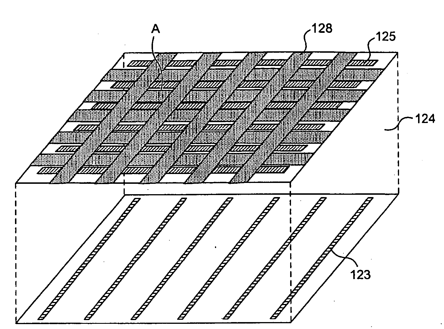
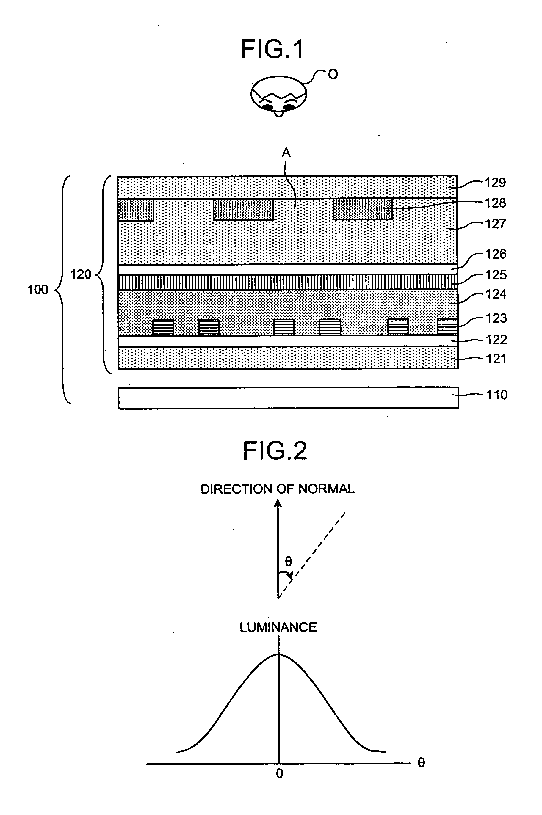
[0041]FIG. 1 is a horizontal cross-sectional diagram schematically depicting a directional backlight 100 according to the present invention. In FIG. 1, an observer O is positioned on a top side, that is, the directional backlight 100 emits light to the top side. The directional backlight 100 can be any one of a flat type and a tilt type. The flat type is installed with a light-emitting surface parallel with the horizontal in a real space. The tilt type is installed in a tilted orientation relative to the horizontal such that the light-emitting surface faces the observer.

[0042]As shown in FIG. 1, the directional backlight 100 includes a surface light source 110 and a polarizing device unit 120 provided above the surface light source 110.

[0043]The surface light source 110 is a planar light source having such a directivity in luminance distribution that luminance distribution are concentrated close to the normal of a light-emitting surface of the surface light source 110. The surface l...

second embodiment

[0071]FIG. 8 is a horizontal cross-sectional diagram schematically depicting an image display apparatus 200 according to the In FIG. 8, the observer is positioned on a top side, that is, the directional backlight 100 emits light to the top side. The image display apparatus 200 can be any one of a flat type and a tilt type. The flat type is installed with an image-display surface (light-emitting surface) parallel with the horizontal in a real space. The tilt type is installed in a tilted orientation relative to the horizontal so that the image display surface faces the observer O.

[0072]As shown in FIG. 8, the image display apparatus 200 includes the surface light source 110, the polarizing device unit 120 provided above the surface light source 110, and a liquid crystal display (LCD) panel 210 provided above the polarizing device unit 120.

[0073]The LCD panel 210 includes a light-transmissive polarizing plate 211, a liquid crystal cell 212 on the polarizing plate 211, and a light-tra...

third embodiment

[0106]FIG. 19 is a horizontal cross-sectional diagram schematically depicting a stereoscopic display apparatus 300 according to the In FIG. 19, the observer is positioned on a top side, that is, the directional backlight 100 emits light to the top side. The stereoscopic display apparatus 300 can be any one of a flat type and a tilt type. The flat type is installed with an image-display surface (light-emitting surface) parallel with the horizontal in a real space. The tilt type is installed in a tilted orientation relative to the horizontal so that the image display surface faces the observer O.

[0107]As shown in FIG. 19, the stereoscopic display apparatus 300 includes the surface light source 110, the polarizing device unit 120 that faces the surface light source 110, and the LCD panel 210 that faces the polarizing device unit 120, and a parallax creating element 310 that faces the LCD panel 210.

[0108]The parallax creating element 310 is an optical element, such as a lenticular plat...


PUM

PropertyMeasurementUnit
orientation angleaaaaaaaaaa
sizeaaaaaaaaaa

Abstract

A stereoscopic display apparatus includes a liquid-crystal display device that has display pixels arranged in a matrix and displays an elemental image array formed from a plurality of field images on the display pixels to render stereoscopic display, a parallax creating unit provided on the front surface or the rear surface of the liquid-crystal display device, and a directional backlight that emits light through the liquid-crystal display device then through the parallax creating unit and switches directions of the thus-emitted light among a plurality of directions according to a display of the field image is disclosed.

Description

CROSS-REFERENCE TO RELATED APPLICATIONS[0001]This application is based upon and claims the benefit of priority from the prior Japanese Patent Application No. 2007-218499, filed on Aug. 24, 2007; the entire contents of which are incorporated herein by reference.BACKGROUND OF THE INVENTION[0002]1. Field of the Invention[0003]The present invention relates to a directional backlight, a display apparatus and a stereoscopic display apparatus using the directional backlight.[0004]2. Description of the Related Art[0005]Various systems for implementing stereoscopic display apparatuses, or three-dimensional (3D) image display apparatuses, capable of displaying three-dimensional moving images are known. In recent years, demands for stereoscopic display systems that use a flat panel and do not require special glasses have been increased particularly. A relatively easily implementable system that provides a parallax creating unit is known. The parallax creating unit is provided in immediate fron...

Claims


Application Information

Patent Timeline
Patent Type & Authority Applications(United States)
IPC IPC(8): G02F1/13357G02B30/25G02B30/27
CPCG02B27/2214G02F1/133606G09G3/003G09G3/20H04N13/045G09G3/3648H04N13/0404H04N13/0411H04N13/0418G09G3/3413H04N13/305H04N13/32H04N13/312H04N13/354G02B30/27
Inventor KASHIWAGI, MASAKOSAISHU, TATSUOFUKUSHIMA, RIEKO
Owner KK TOSHIBA
Why Eureka
Try Eureka