
Dynamic user interface for displaying connection status and method thereof

a dynamic user interface and connection status technology, applied in the field of electronic devices, can solve the problems of confusion of soft keys, increased features of electronic devices, and difficulty in displaying connection status,

Inactive Publication Date: 2009-02-26
GOOGLE TECH HLDG LLC
View PDF6 Cites 30 Cited by
  • Summary
  • Abstract
  • Description
  • Claims
  • Application Information

AI Technical Summary

Problems solved by technology

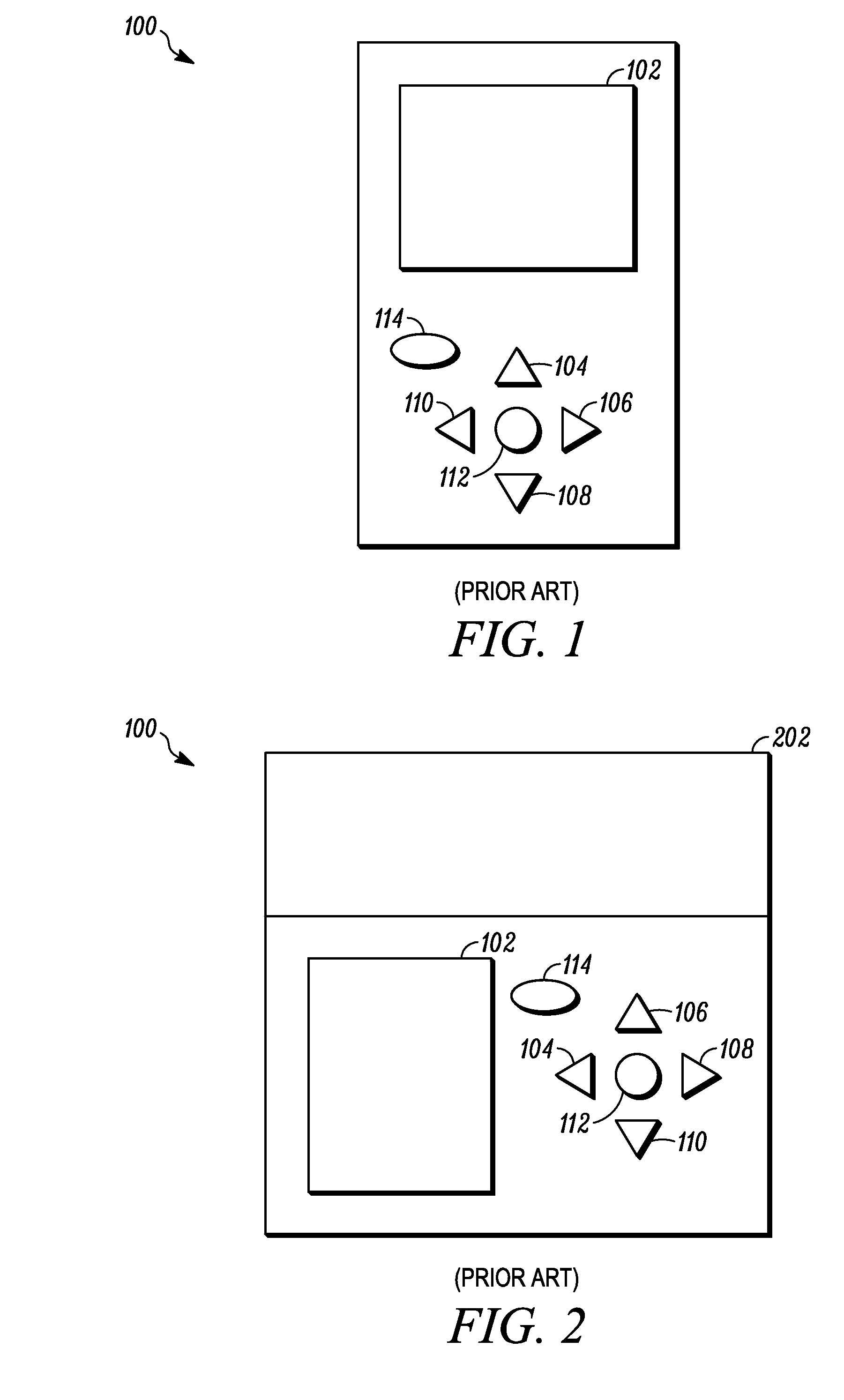
Furthermore, as technology advances, new features continue to be added to electronic devices, which are also becoming smaller.
One problem with soft keys, however, is that users must mentally map the button to the label displayed on the screen, i.e., a person must look at the screen for the indication as to the functional operation of a soft key.
Thus, some users find soft keys confusing.
Touch screens are not without problems, however.
For example, touch screens tend to be expensive, and touch screens are not always feasible to implement in electronic devices, especially in smaller electronic devices.
Additionally, touch screens do not offer other benefits, such as haptic feedback.
For stylus-driven touch screens, the user must use two hands to control the device, which can be disadvantageous, and for finger-driven touch screens, the screens are typically large and unsuitable for use in mobile devices.

Method used


Image

  • Dynamic user interface for displaying connection status and method thereof
  • Dynamic user interface for displaying connection status and method thereof
  • Dynamic user interface for displaying connection status and method thereof

Examples


Embodiment Construction

[0023]The following detailed description is merely exemplary in nature and is not intended to limit the subject matter or the application and uses of the disclosure. Furthermore, there is no intention to be bound by any theory presented in the preceding background section or the following detailed description. Instead, the disclosure within will provide one skilled in the art a convenient road map for implementing the disclosure, it being understood that various changes may be made in the function and arrangement of elements or methods described without departing from the scope or spirit of the disclosure as set forth in the appended claims.

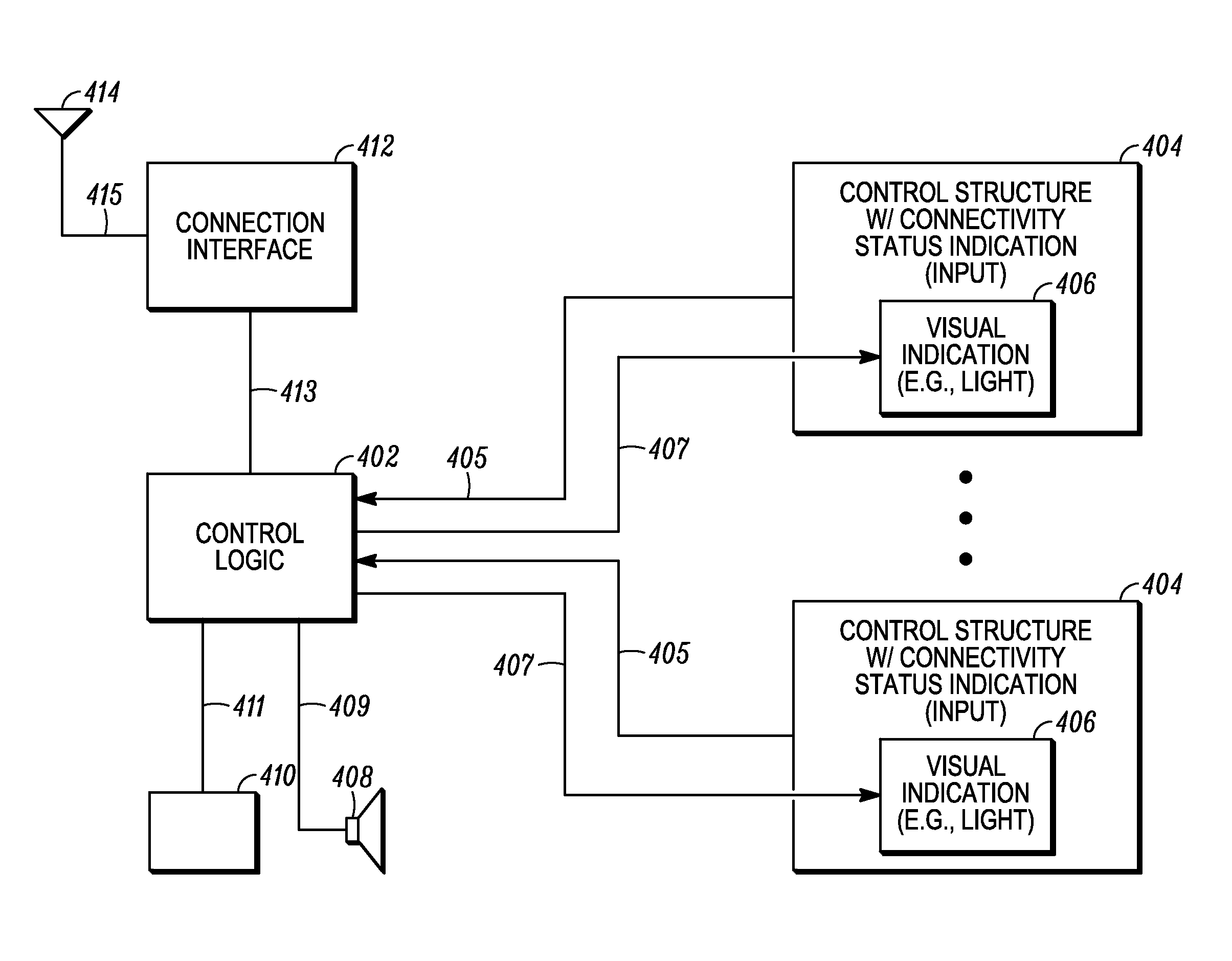
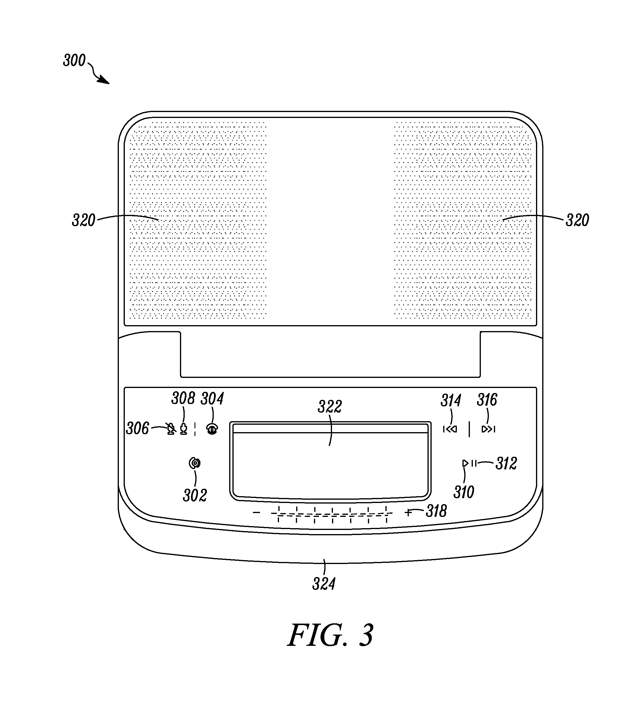
[0024]An electronic device has a plurality of different control structures, each with corresponding visual indication of connectivity status with a remote device such as short range wireless headset or other device. Control logic, operatively coupled to the plurality of different control structures and corresponding visual indications, is operati...


PUM


Abstract

A method for providing a user interface for a device (300) includes determining a capability of a remote device, selectively enabling at least one of a plurality of different control structures (404, e.g., 302, 310, etc.), each with corresponding visual indication (406) of connectivity status based on a connection occurring and determined capability of the remote device. The method may also include selectively enabling a second control structure (404, e.g., 302, 310, etc.) of the plurality of different control structures, the second control structure also with corresponding visual indication (406) of connectivity status. The method may also include selectively disabling at least one of the plurality of different control structures (404, e.g., 302, 310, etc.) with corresponding visual indication (406) of connectivity status based on a change in a connection status. Furthermore, a device 300 may implement the disclosed methods.

Description

FIELD OF THE DISCLOSURE[0001]The disclosure relates generally to electronic devices and more particularly to electronic devices that employ a user interface.BACKGROUND OF THE DISCLOSURE[0002]Electronic devices, such as computers, media, e.g., music, players, laptops, wireless handheld devices such as cell phones, digital music players, palm computing devices, or any other suitable devices are increasingly becoming widespread. Improved usability of such devices can increase sales for sellers as consumer demand can be driven by differing device usability characteristics and device features. Furthermore, as technology advances, new features continue to be added to electronic devices, which are also becoming smaller. As more features are added to smaller devices, however, users must be able to more easily (and more frequently) interact with such devices via understandable and efficient means.[0003]Morphable user interfaces are thus beginning to be an important design consideration for t...

Claims


Application Information

Patent Timeline
Patent Type & Authority Applications(United States)
IPC IPC(8): H04B7/00G05B19/00
CPCG06F3/01
Inventor JOBLING, JEREMY T.PARK, JOONWOOSLOCUM, JEREMY S.
Owner GOOGLE TECH HLDG LLC
Learn More