Selectable Aiming Pattern for an Imaging-Based Bar Code Reader

a bar code reader and aiming pattern technology, applied in the field of aiming pattern assembly for imaging-based bar code readers, can solve the problems of parallax between the imaging system field of view fv and the aiming pattern, poor resolution of the imaged target bar code, and lens assembly adds additional complications, so as to facilitate the aiming of the reader

Active Publication Date: 2009-03-05
SYMBOL TECH LLC
View PDF3 Cites 61 Cited by
  • Summary
  • Abstract
  • Description
  • Claims
  • Application Information

AI Technical Summary

Problems solved by technology

Because the aiming pattern assembly is not coaxially aligned with the imaging system in the reader housing, this results in parallax between the imaging system field of view FV and the aiming pattern.
At the near and far limits of the working range WR, there is a problem with blurriness, that is, poor resolution of the imaged target bar code.
In addition to parallax, a variable focus imaging lens assembly adds additional complications to problem of the aiming pattern being congruent with the imaging assembly field of view FV.
That is, the periphery of the block-type aiming pattern would not accurately represent both the bounds of the narrow angle field of view and the wide angle field of view.

Method used


Image

  • Selectable Aiming Pattern for an Imaging-Based Bar Code Reader
  • Selectable Aiming Pattern for an Imaging-Based Bar Code Reader
  • Selectable Aiming Pattern for an Imaging-Based Bar Code Reader

Examples


Embodiment Construction

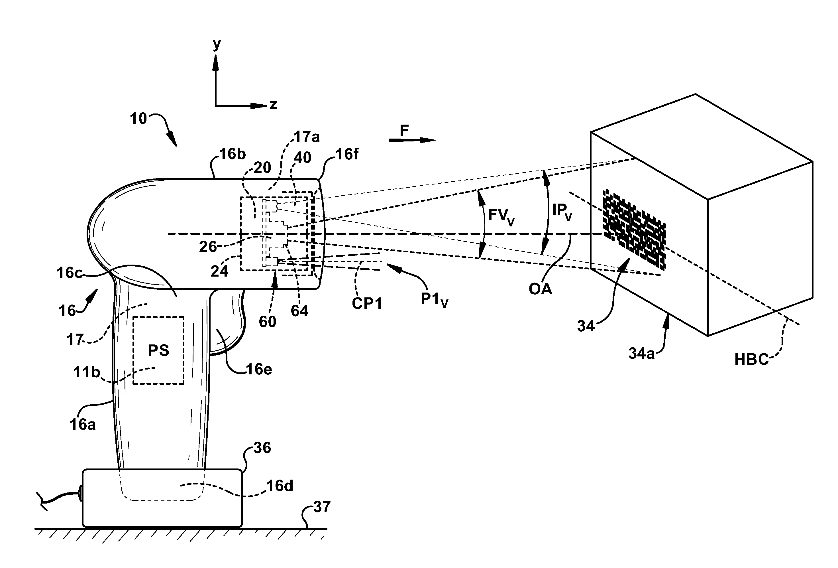
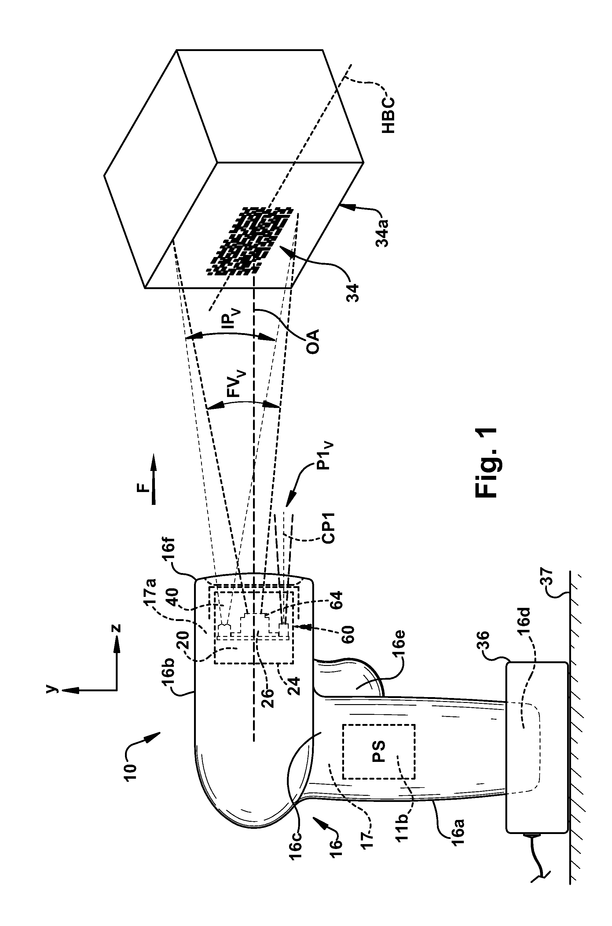
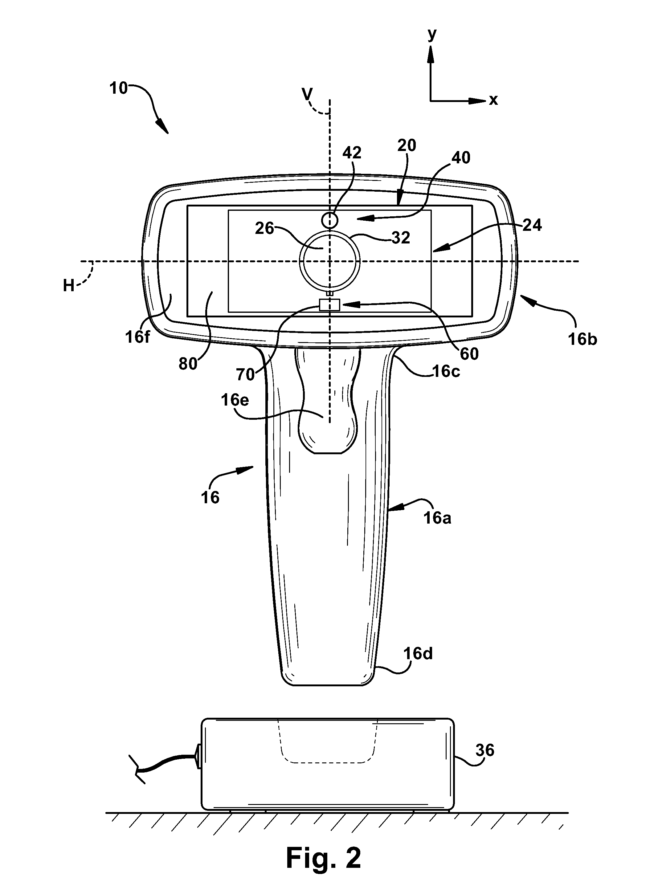
[0044]A first exemplary embodiment of an imaging-based bar code reader of the present invention is shown schematically at 10 in FIGS. 1-6. The bar code reader 10 includes an imaging system 12 and a decoding system 14 mounted in a housing 16. The reader 10 is capable of reading, that is, imaging and decoding bar codes. The imaging system 12 is adapted to capture image frames of a field of view FV of the imaging system 12 and the decoding system 14 is adapted to decode encoded indicia within a captured image frame. The housing 16 supports circuitry 11 of the reader 10, including the imaging and decoding systems 12, 14 within an interior region 17 of the housing 16. The housing 16 also supports an illumination assembly 40 for illuminating the field of view FV and an aiming pattern assembly 60 to facilitate a user properly aiming the housing 16 at a target object, such as a target bar code 34. Advantageously, as will be discussed below, the aiming pattern assembly 60 of the present inve...


PUM


Abstract

An aiming pattern assembly (60) for an imaging-based bar code reader (10) including: a light source assembly (62) generating focused light; a pattern shaping assembly (66) receiving focused light from the light source assembly (62) and including a first area (66a) and a non-overlapping second area (66b), focused light passing through the first area (66a) creating a first aiming pattern (P1) projected toward a field of view (FV) and passing through the second area (66b) creating a second aiming pattern (P2) projected toward the field of view (FV); and a pattern selection assembly (68) receiving the first and second aiming patterns (P1, P2) and passing at least one of the first and second aiming patterns (P1, P2).

Description

FIELD OF THE INVENTION[0001]The present invention relates to an aiming pattern assembly for an imaging-based bar code reader and, more particularly, to an aiming pattern assembly for an imaging-based bar code reader selectively providing at least two different aiming patterns for near and far target distances.BACKGROUND ART[0002]Various electro-optical systems have been developed for reading optical indicia, such as bar codes. A bar code is a coded pattern of graphical indicia comprised of a series of bars and spaces of varying widths, the bars and spaces having differing light reflecting characteristics. Some of the more popular bar code symbologies include: Uniform Product Code (UPC), typically used in retail stores sales; Data Matrix, typically used for labeling small electronic products; Code 39, primarily used in inventory tracking; and Postnet, which is used for encoding zip codes for U.S. mail. Bar codes may be one dimensional (ID), i.e., a single row of graphical indicia suc...

Claims


Application Information

Patent Timeline
Patent Type & Authority Applications(United States)
IPC IPC(8): G02B26/10G06K7/10
CPCG06K2207/1011G02B27/20
Inventor VINOGRADOV, IGORTRAJKOVIC, MIROSLAV
Owner SYMBOL TECH LLC
Why Eureka
Try Eureka