Wrapping sheet

a wrapping sheet and folding technology, applied in the field of wrapping sheets, can solve the problems of inability to adjust the position of wrapping sheets during the folding process, and achieve the effect of convenient and smooth folding and compact shap

Active Publication Date: 2009-03-05
TOYODA GOSEI CO LTD
View PDF3 Cites 31 Cited by
  • Summary
  • Abstract
  • Description
  • Claims
  • Application Information

AI Technical Summary

Benefits of technology

[0008]To resolve the above problem, one objective of the present invention is to provide a wrapping sheet that ensures an air bag folding process can be easily and steadily performed until the folding has been completed and a predetermined shape obtained.

Problems solved by technology

With the conventional wrapping sheets referenced above, although each of these wrapping sheets can satisfactorily wrap and prevent the disarrangement of a folded air bag, adjusting the position of such a wrapping sheet during a folding process is not possible.

Method used


Image

  • Wrapping sheet
  • Wrapping sheet
  • Wrapping sheet

Examples


first embodiment

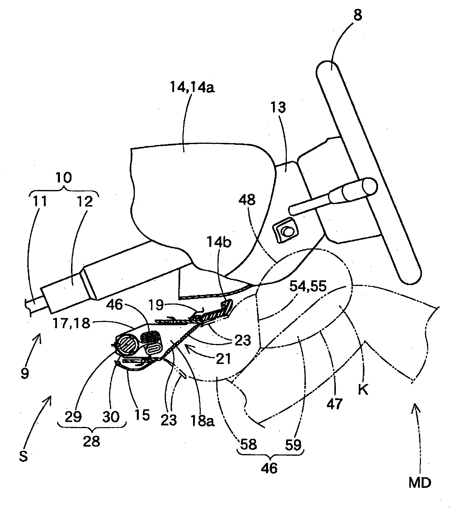
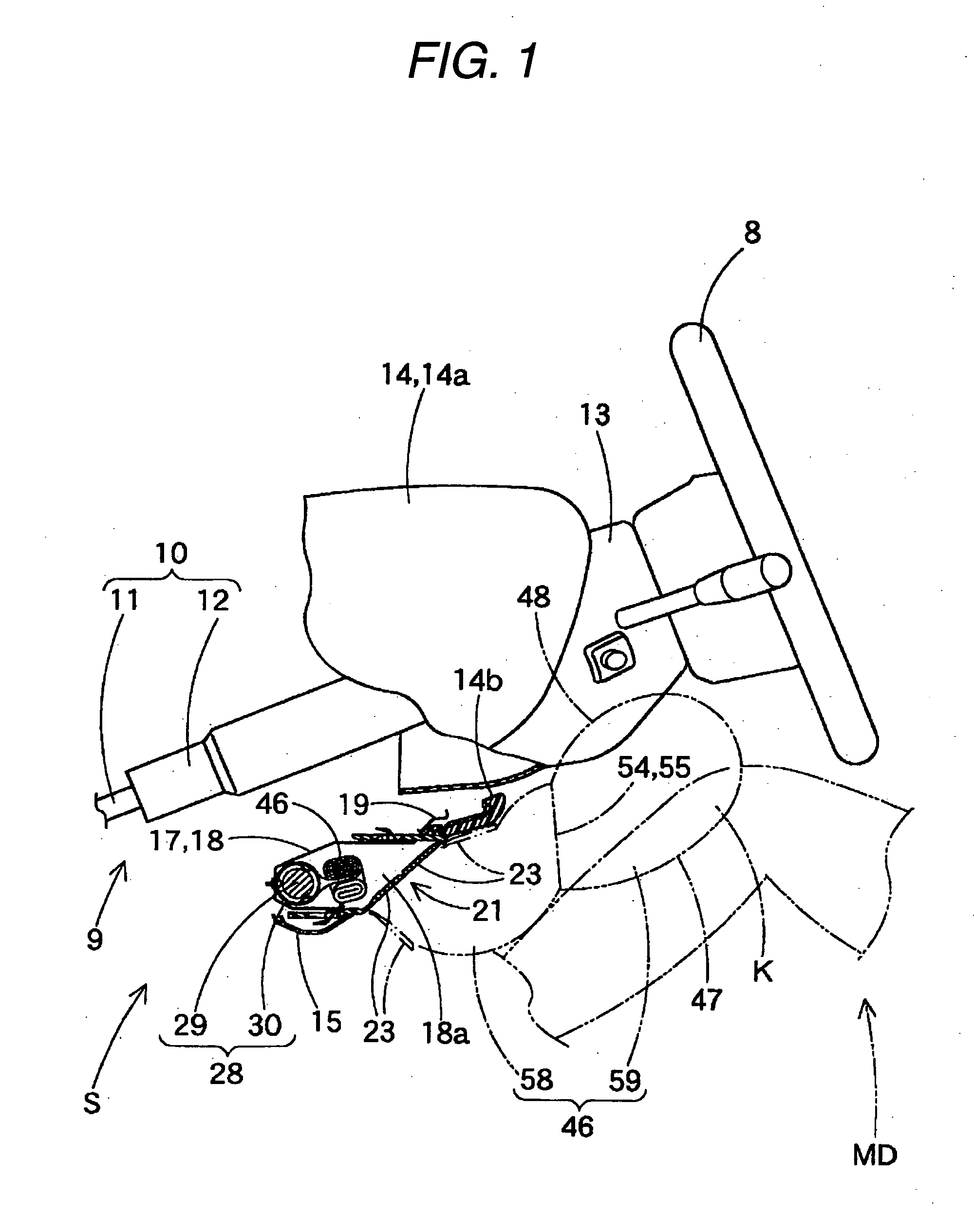
[0040]The preferred embodiments of the present invention will now be described while referring to drawings. According to this invention, as shown in FIG. 2, a wrapping sheet 61 is employed to prevent the disarrangement of the shape of a folded air bag 46 for a knee protection air bag system S. As shown in FIGS. 1 and 4, the knee protection air bag system S, for protecting the knees K of a vehicle driver MD, is provided below a steering column 9 to the front of the vehicle driver MD.

[0041]As shown in FIG. 1, the steering column 9 includes: a column main body 10 coupled with a steering wheel 8; and a column cover 13 provided to cover the column main body 10, which extends forward and obliquely downward from below the steering wheel 8. The column main body 10 is formed of a main shaft 11 and a column tube 12, which circumferentially covers the main shaft 11. The column cover 13 is a nearly square synthetic resin sleeve that extends toward the rear, in the axial direction of the column ...

second embodiment

[0082]Following this, as shown in FIG. 9 (C), the folding form control portion 66A is pulled (actually, the engagement portion 62A on the upper edge 61a side is pulled) to form the convex fold 75, so that a space near the rear of the inflator 28 can be provided for the air bag 46. Then, as shown in FIG. 9D, the auxiliary engagement portions 70A of the folding form control portion 66A are fitted on the attachment shafts 31 by being inserted into engagement holes 70a. In this state, the folding form control portion 66A, which extends from the coupled portion 64A to the auxiliary engagement portion 70A, serves as the fold setting portion 68, and forms the fold 75 by being pulled. At the same time, in the area from the coupled portion 64A to the auxiliary engagement portion 70A, a folded portion 72 is pressed against the inflator 28, and enclosed to prevent the shape of the folded portion from being deteriorated. That is, in second embodiment, the folding form control portion 66A extend...

third embodiment

[0090]The processing for folding the air bag 46 using the wrapping sheets 61B and 81 of the third embodiment will now be described. As shown in FIG. 12A, the inflator 28 is stored within the air bag 46, and bolts 30c, which serve as the attachment shafts 31, project outward through attachment holes 48a and one end of a main body 29 protrudes outward through insertion hole 48b.

[0091]Following this, the lateral folding process is performed as shown in FIG. 12 (A and B). That is, horizontal folds LF are formed to reduce the flattened, vertical size of an air bag 46 and produce a folded portion 72. In this embodiment, the portion nearest an upper edge 46a is folded toward a vehicle-side wall 48 in a manner whereby the upper edge 46a is moved nearer a lower edge 46b and the folded portion 72 is obtained. At this time, the folding will have been completed for an entire downstream chamber 59, i.e., the portion of the air bag 46 extending from the upper edge 46a to the coupled portion 64, ...


PUM


Abstract

A wrapping sheet is to be torn by the inflation of an air bag. Since attachment shafts, used to hold the folded air bag in position, are projected from the air bag, an engagement portion of the wrapping sheet is fitted on the attachment shafts, and the shape of a folding completed body of the air bag is maintained. The wrapping sheet includes not only the engagement portion, but also a coupled portion to be connected to the air bag, and a folding form control portion, which has an auxiliary engagement portion to be fitted on the attachment shafts. When the auxiliary engagement portion is fitted on the attachment shafts, the shape of the air bag that is being folded is adjusted.

Description

BACKGROUND OF THE INVENTION[0001]1. Field of the Invention[0002]The present invention relates to a wrapping sheet used to wrap and maintain a fully folded air bag, but that, as the air bag is being inflated, tears under the pressure exerted by the expanding air bag.[0003]2. Related Art[0004]Conventionally, a wrapping sheet includes an engagement piece that is fitted on attachment shafts projecting from an air bag, and when the engagement piece for the wrapping sheet has been fitted on the attachment shafts, the air bag, for which folding has been completed, is retained, undisturbed, within the wrapping sheet. The attachment shafts projecting from the air bag can be either retainer bolts or defuser bolts, and are employed to secure the folded air bag in a storage portion. Furthermore, one presently available conventional wrapping sheet has not only as a function for preventing the disarrangement of a folded air bag, but also as a protective cover, which when the folded air bag is inf...

Claims


Application Information

Patent Timeline
Patent Type & Authority Applications(United States)
IPC IPC(8): B60R21/16B60R21/20B60R21/201B60R21/237
CPCB60R21/20B60R2021/23169B60R21/237B60R21/201
Inventor ISHIDA, RYOTAROANDO, TAKESHINONOYAMA, YOSHINORIITO, MICHIYASU
Owner TOYODA GOSEI CO LTD
Why Eureka
Try Eureka