Multi-planar obturator with foldable retractor

a multi-planar obturator and retractor technology, applied in the field of multi-planar obturators with foldable retractors, can solve the problems of difficult positioning of large surgical access devices in the incision, damage to a smaller incision, etc., and achieve the effect of increasing the size of the pathway

a multi-planar obturator and retractor technology, applied in the field of multi-planar obturators with foldable retractors, can solve the problems of difficult positioning of large surgical access devices in the incision, damage to a smaller incision, etc., and achieve the effect of increasing the size of the pathway

US20100312062A1Active Publication Date: 2010-12-09CILAG GMBH INT

Image

  • Multi-planar obturator with foldable retractor
  • Multi-planar obturator with foldable retractor
  • Multi-planar obturator with foldable retractor

Examples


Embodiment Construction

[0029]Certain exemplary embodiments will now be described to provide an overall understanding of the principles of the structure, function, manufacture, and use of the devices and methods disclosed herein. One or more examples of these embodiments are illustrated in the accompanying drawings. Those of ordinary skill in the art will understand that the devices and methods specifically described herein and illustrated in the accompanying drawings are non-limiting exemplary embodiments and that the scope of the present invention is defined solely by the claims. The features illustrated or described in connection with one exemplary embodiment may be combined with the features of other embodiments. Such modifications and variations are intended to be included within the scope of the present invention.

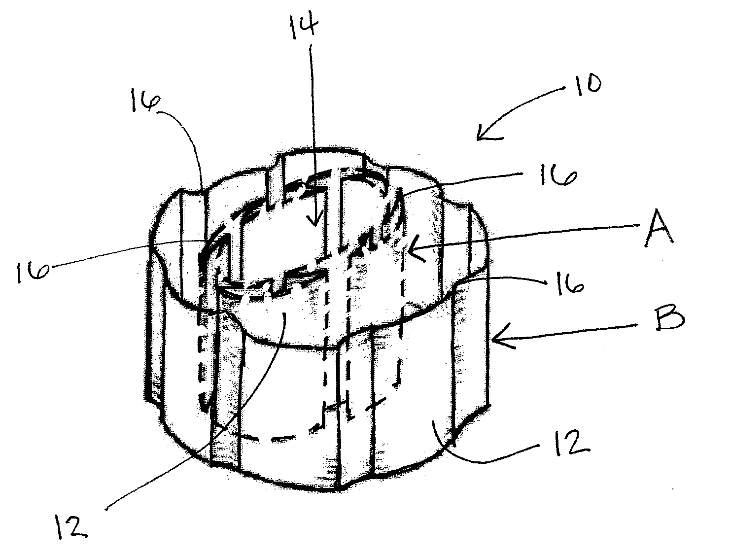
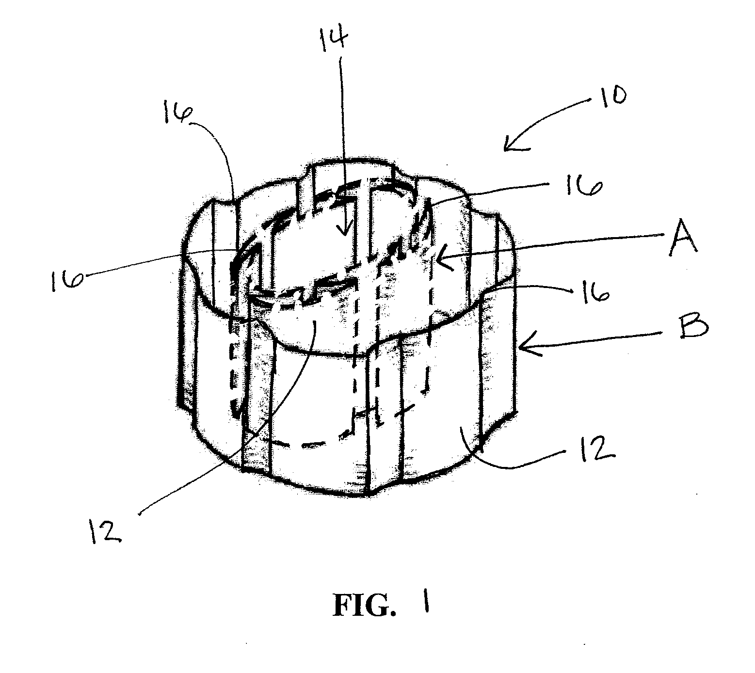
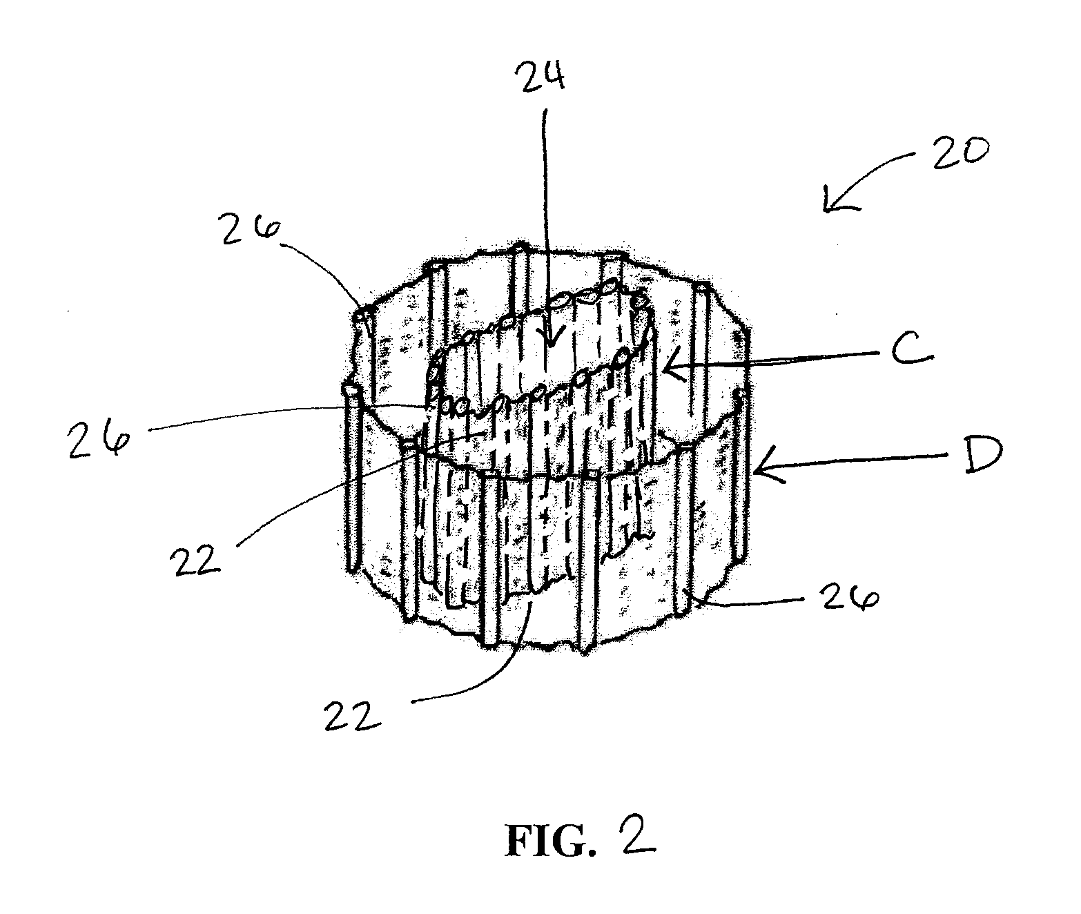
[0030]The present invention generally provides improved methods and devices for providing access into a body cavity, particularly through small incisions and / or small openings in body tissue...


PUM


Abstract

Various methods and devices are provided for providing surgical access to a body cavity using a surgical access device that can include an elongate flexible member having proximal and distal ends and a sidewall extending therebetween. The elongate flexible member can be movable between a first position in which the elongate flexible member has at least one longitudinal fold formed in the sidewall such that a width of a longitudinal opening extending through the elongate flexible member is reduced, and a second position in which the fold in the sidewall is unfolded such that a width of the longitudinal opening is increased. In some embodiments, an obturator having expansion members can be used to unfold the elongate flexible member.

Description

FIELD OF THE INVENTION[0001]The present invention relates to methods and devices for providing surgical access into a body cavity.BACKGROUND OF THE INVENTION[0002]Access ports are widely used in medical procedures to gain access to anatomical cavities ranging in size from the abdomen to small blood vessels, such as veins and arteries, epidural, pleural and subarachnoid spaces, heart ventricles, and spinal and synovial cavities. The use of access ports has become more common as they provide minimally invasive techniques for establishing a portal for a number of procedures, such as those involving the abdominal cavity. Reduced postoperative recovery time, markedly decreased post-operative pain and wound infection, and improved cosmetic outcome are well established benefits of minimally invasive surgery, derived mainly from the ability of surgeons to perform an operation utilizing smaller incisions of the body cavity wall.[0003]In many surgical procedures, it is desirable to provide on...

Claims


Application Information

Patent Timeline
09 Dec 2010
Publication
US20100312062A1
IPC
A61B1/32
CPC
A61B17/02; A61B17/3423; A61B17/3431; A61B2017/00477; A61B2017/346; A61B2017/3466; A61B17/3439
Inventors
CROPPER, MICHAEL S.; SHELTON, IV, FREDERICK E.