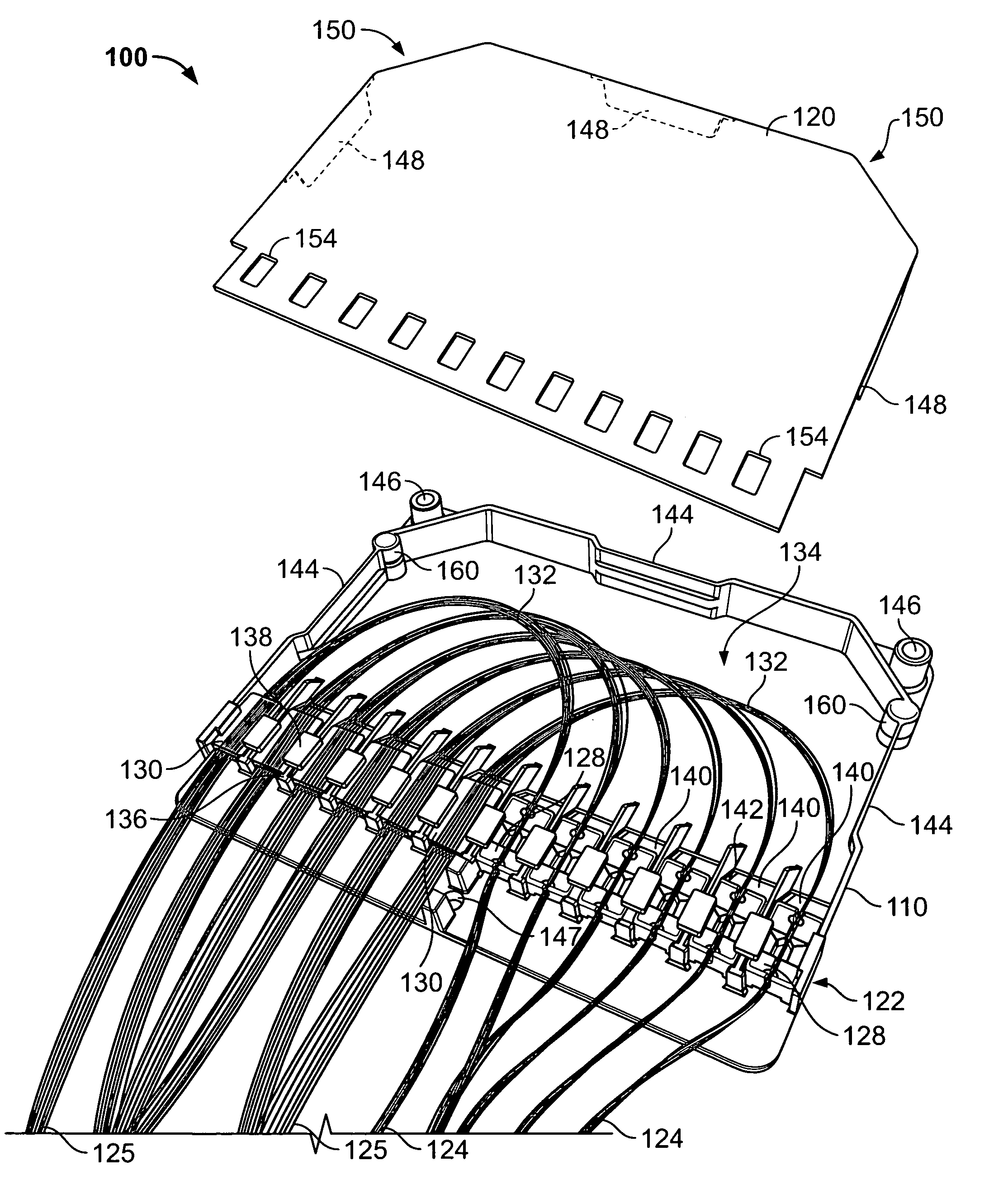
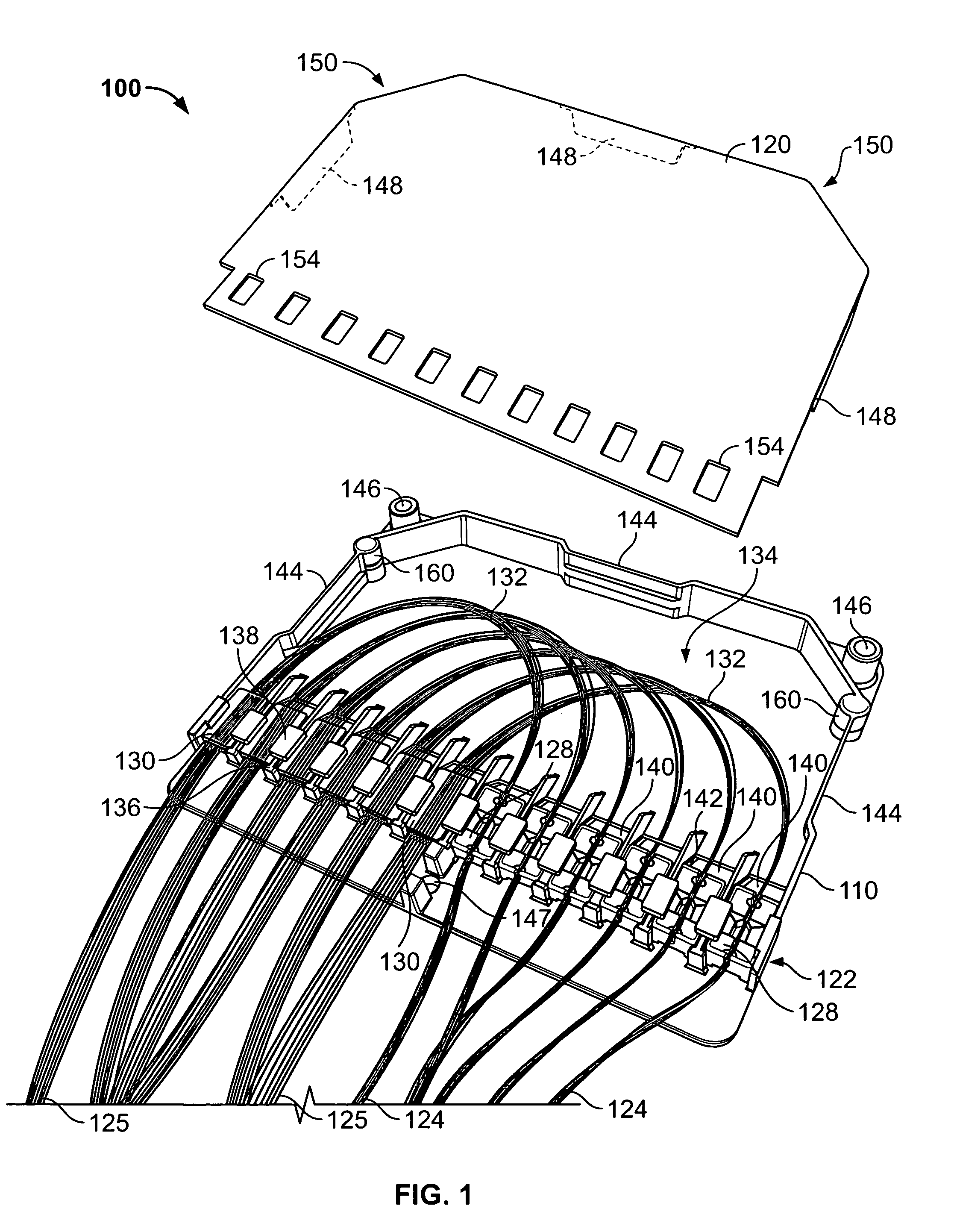
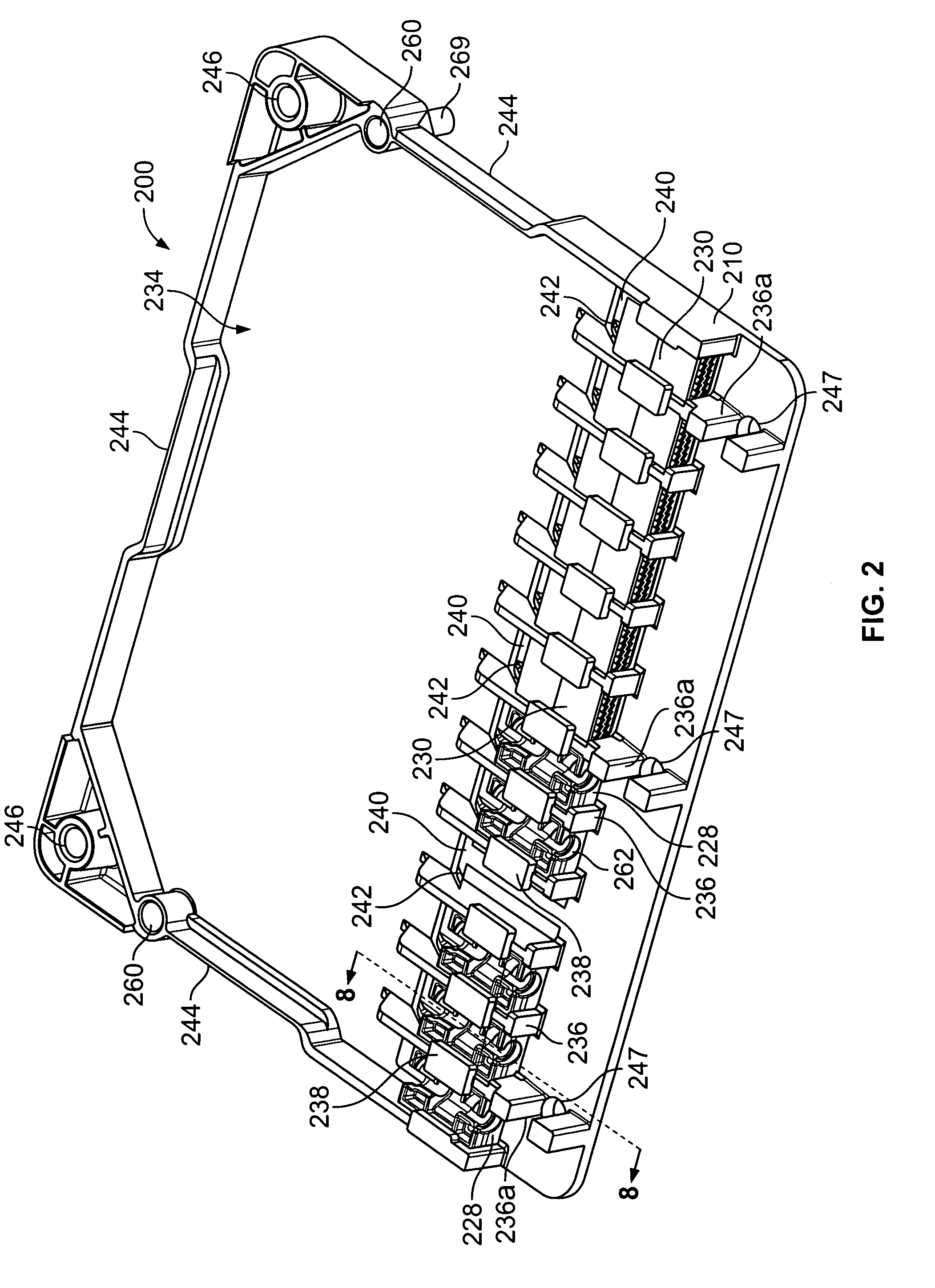
Optical fiber fanout devices and methods for forming the same

a technology of optical fiber and fanout, which is applied in the direction of optics, fiber mechanical structures, instruments, etc., can solve the problem that the loss of optical fibers in a fanout can increase to unacceptable levels

Active Publication Date: 2009-03-05
COMMSCOPE TECH LLC
View PDF7 Cites 113 Cited by
  • Summary
  • Abstract
  • Description
  • Claims
  • Application Information

AI Technical Summary

Benefits of technology

[0015]In some embodiments, the furcation tubes are adhesively secured in the furcation tube holding block and the furcation tube holding block is configured to limit movement of the furcation tubes in a direction causing peeling of the adhesive in the furcation tube holding block. The plurality of optical fibers are adhesively secured in the multi-fiber holding block and the multi-fiber holding block is configured to limit movement of the pl

Problems solved by technology

When exposed to typically specified low temperature environments (i.e., −40° C.)

Method used


Image

  • Optical fiber fanout devices and methods for forming the same
  • Optical fiber fanout devices and methods for forming the same
  • Optical fiber fanout devices and methods for forming the same

Examples


Embodiment Construction

[0028]The present invention now will be described more fully hereinafter with reference to the accompanying drawings, in which illustrative embodiments of the invention are shown. In the drawings, the relative sizes of regions or features may be exaggerated for clarity. This invention may, however, be embodied in many different forms and should not be construed as limited to the embodiments set forth herein; rather, these embodiments are provided so that this disclosure will be thorough and complete, and will fully convey the scope of the invention to those skilled in the art.

[0029]It will be understood that, although the terms first, second, etc. may be used herein to describe various elements, components, regions, layers and / or sections, these elements, components, regions, layers and / or sections should not be limited by these terms. These terms are only used to distinguish one element, component, region, layer or section from another region, layer or section. Thus, a first elemen...


PUM


Abstract

Optical fiber fanout devices include a housing having a fiber telescoping cavity therein. An optical fiber tubing receiving opening in the housing extends to the fiber telescoping cavity. The optical fiber tubing receiving opening is configured to secure a plurality of optical fiber tubes therein. An optical fiber receiving opening in the housing also extends to the cavity. The optical fiber receiving opening is displaced from the optical fiber tubing receiving opening by a distance selected to define an arc for an optical fiber extending from the optical fiber receiving opening to the optical fiber tubing receiving opening that exceeds a minimum bend radius for the optical fiber.

Description

RELATED APPLICATIONS[0001]The present application claims the benefit of and priority from U.S. Provisional Application No. 60 / 966,300 (Attorney Docket No. E-TO-000168US / 5487-260PR), filed Aug. 27, 2007, the disclosure of which is hereby incorporated herein in its entirety by reference.BACKGROUND OF THE INVENTION[0002]The present invention relates to optical fiber products and, more particularly, to optical fiber storage transition products and methods for using the same.[0003]Optical fiber networks are increasingly being installed to support high-speed voice and data communications. Increasingly, the optical fiber coupling is being expanded out from the central office of the communication service provider companies, such as Regional Bell Operating Companies (RBOCs) to the subscriber locations, such as homes or businesses, where conventional copper wiring was conventionally used. Such alternate methods of providing bandwidth to subscriber locations are often referred to in the teleco...

Claims


Application Information

Patent Timeline
IPC IPC(8): G02B6/44
CPCG02B6/4478G02B6/4471
Inventor WRIGHT, WILLIAMRADLIFF, DAVIDADAMS, GARYMULLANEY, JULIAN
Owner COMMSCOPE TECH LLC
Why Eureka
Try Eureka