Fuel injection device and method for examining the same

a fuel injection and fuel technology, applied in the direction of electrical control, process and machine control, instruments, etc., can solve the problem of reflected offset errors

Active Publication Date: 2009-03-05
DENSO CORP
View PDF5 Cites 25 Cited by
  • Summary
  • Abstract
  • Description
  • Claims
  • Application Information

AI Technical Summary

Benefits of technology

[0010]According to another aspect of the present invention, a method for examining a fuel injection system, which includes a fuel injection valve, a pressure sensor for outputting a detection signal, a storage unit for storing individual difference information, and a control unit for controlling the fuel injection valve based on the stored individual difference information and the detection signal, the method comprises applying test pressure including first and second test pressure to the pressure sensor so as to obtain first and second detection signals, which respectively correspond to the first and second test pressure. The method further comprises calculating a difference between the first and second test pressure as a test pressure change. The method further comprises calculating a difference between the first and second detection signals as a detection signal change. The method further comprises storing individual difference information, which indicates a relationship between the test pressure change and the detection signal change, as an output characteristic of the detection signal in the storage unit.
[0011]According to another aspect of the present invention, a method for examining a fuel injection

Problems solved by technology

First, test pressure is generated using a test apparatus such as a pressure generator.
However, the generated test pressure does not necessarily coincide with target pressure, which is supposed to be generated, and an offset error may be caused in test pressure.
Thus, the off

Method used


Image

  • Fuel injection device and method for examining the same
  • Fuel injection device and method for examining the same
  • Fuel injection device and method for examining the same

Examples


embodiment

[0018

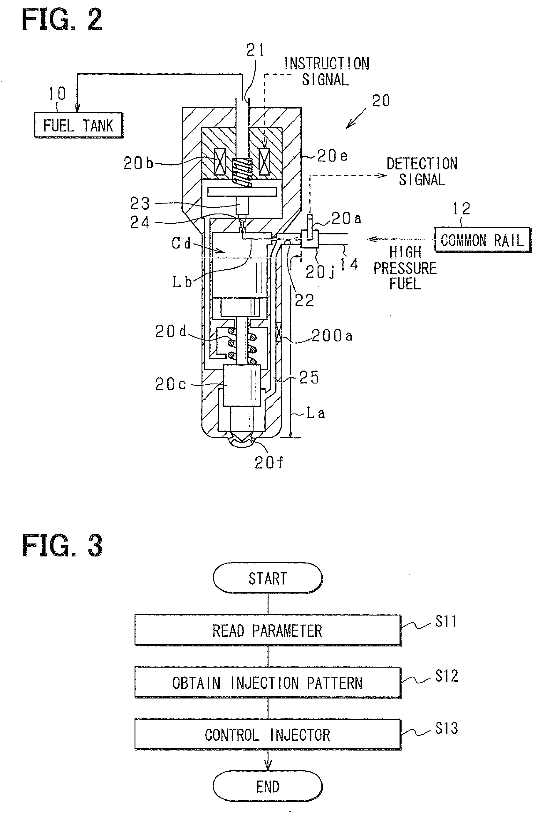
[0019]An embodiment embodying a fuel injection device and a fuel injection system will be described below with reference to drawings. A fuel injection device according to the present embodiment is mounted to, for example, a common-rail fuel injection system for an internal combustion engine for an automobile. For example, the present fuel injection device is used for directly injecting high-pressure fuel to a combustion chamber in a cylinder of a diesel engine. The high-pressure fuel is, for example, light oil, which is at injection pressure more than 100 MPa.

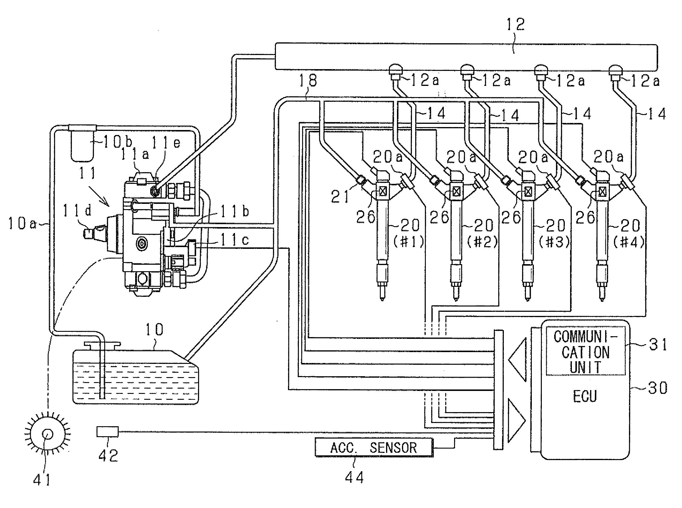
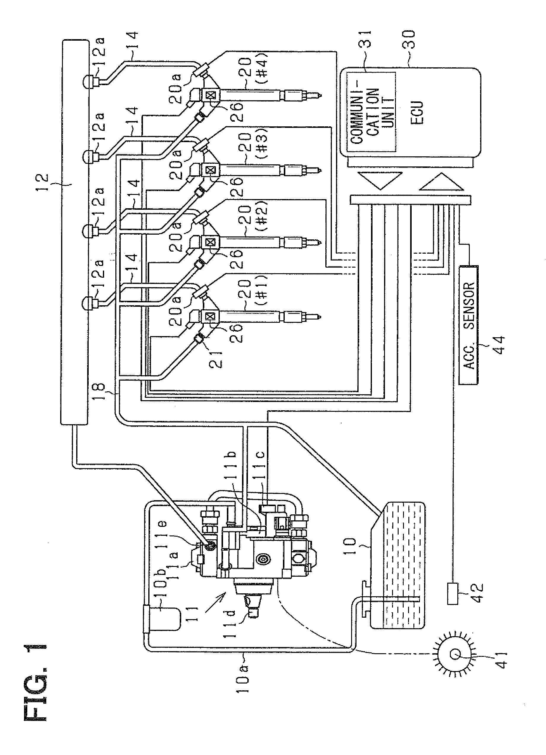
[0020]First, the common-rail fuel injection system as an in-vehicle engine system according to the present embodiment is described with reference to FIG. 1. In the present embodiment, the engine is, for example, a multi-cylinder engine such as an inline four-cylinder engine. Specifically, the engine may be a four-stroke reciprocal diesel engine. In the present engine, an electromagnetic pickup as a cylinder-detection senso...


PUM


Abstract

A fuel injection device includes a fuel injection valve for injecting fuel. A pressure sensor is configured to output detection signal correspondingly to pressure of the fuel. The fuel injection device further includes a storage unit for storing individual difference information, which indicates an output characteristic of the detection signal. The output characteristic is obtained by an examination. The individual difference information indicates a relationship between change in test pressure and change in detection signal. The test pressure is actually applied to the pressure sensor in the examination. The change in detection signal is attributed to the change in test pressure.

Description

CROSS REFERENCE TO RELATED APPLICATIONS[0001]This application is based on and incorporates herein by reference Japanese Patent Application No. 2007-227119 filed on Aug. 31, 2007.FIELD OF THE INVENTION[0002]The present invention relates to a fuel injection device having a fuel injection valve for injecting fuel, which is distributed from a pressure-accumulation injection device.BACKGROUND OF THE INVENTION[0003]Conventionally, a fuel injection valve is provided to an internal combustion engine for injecting fuel so as to perform combustion in an engine. For example, according to JP-A-2006-200378, a pressure sensor is provided to a fueling path for detecting pressure of fuel in the fueling path so as to control the fuel injection valve based on the detected pressure.[0004]The pressure sensor is configured to output a detection signal according to the pressure of fuel. The output characteristic of the detection signal has an individual difference. For example, when two different pressur...

Claims


Application Information

Patent Timeline
IPC IPC(8): F02D41/30
CPCF02D41/2474F02D41/3836G01L27/002F02M57/005F02M2200/24F02D2200/0602G01L27/005
Inventor NAKATA, KENICHIROISHIZUKA, KOJI
Owner DENSO CORP
Why Eureka
Try Eureka