Head-mounted device

a head-mounted device and mounting mechanism technology, applied in the direction of optics, instruments, electrical equipment, etc., can solve the problems of user discomfort, device size and heavy weight, complicated operation of wearing the head-mounted device, etc., to simplify the operation of wearing and reduce the weight of the head-mounted device

Inactive Publication Date: 2009-03-12
CANON KK
View PDF12 Cites 29 Cited by
  • Summary
  • Abstract
  • Description
  • Claims
  • Application Information

AI Technical Summary

Benefits of technology

[0009]The present invention is directed to a mounting mechanism of a HMD which can reduce weight of the HMD, allow a use...

Problems solved by technology

However, the mounting mechanism discussed in Japanese patent Application Laid-Open No. 8-088814 provides adjustment mechanisms for a head circumference pressing unit and for the parietal region pressing unit separately, and operations for wearing the HMD becomes complicated.
Further, since there is a plurality of adjustment me...

Method used


Image

  • Head-mounted device
  • Head-mounted device
  • Head-mounted device

Examples


first exemplary embodiment

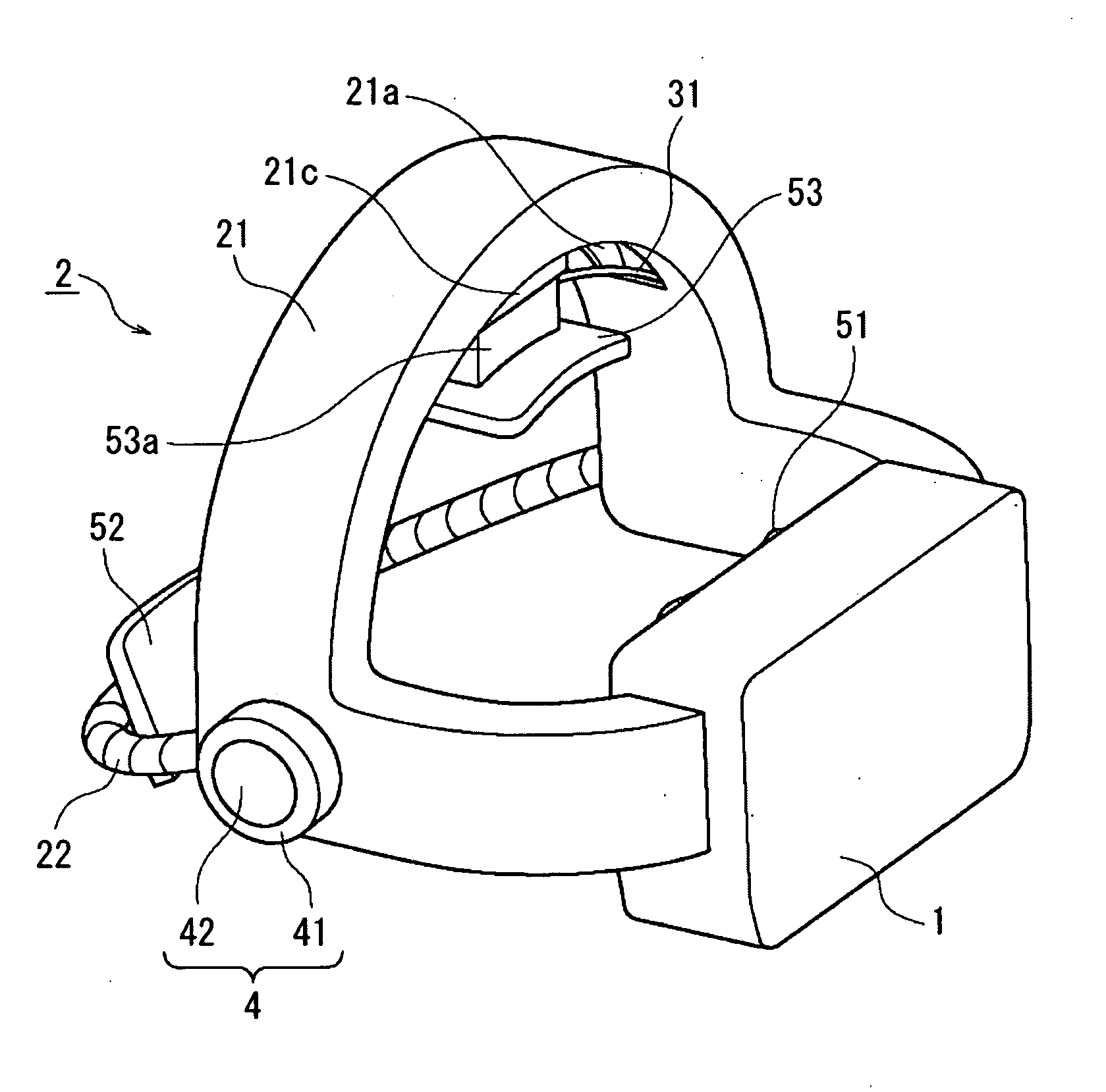
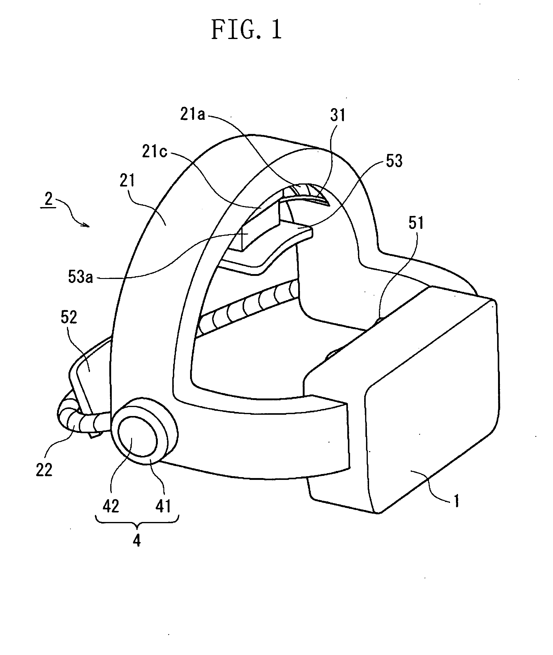
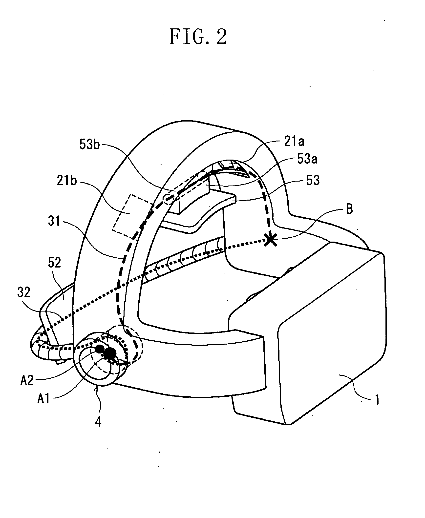
[0030]FIGS. 1 and 2 illustrate perspective views of an HMD according to a first exemplary embodiment of the present invention. FIG. 3 and FIG. 4 illustrate an elevation view and a side view of the HMD respectively.

[0031]The HMD according to the first exemplary embodiment includes a display unit 1 and a mounting unit 2 which holds the display unit 1 in front of eyes of a user. The display unit 1 includes a display element (not illustrated) which internally displays images, and an optical system (not illustrated) which enlarges the images in the display element and guides the images to the eyes of the user.

[0032]Further, the display unit 1 is connected to a frame 21 that extends along a head circumference from a right side to a left side by crossing over the parietal region. The frame 21 has a hollow architecture which can realize rigidity and weight saving at the same time. Further, holes 21a and 21b are formed on the parietal region of the frame 21 for running a wire 31 through. In ...

second exemplary embodiment

[0061]FIG. 9 illustrates a perspective view of an HMD according to a second exemplary embodiment of the present invention. The turning directions for winding up the wire 31 and the wire 32 are the same in FIG. 2. FIG. 9 is different from FIG. 2 in that the turning directions are opposite in FIG. 9. FIG. 10 illustrates a side view of the HMD according to the second exemplary embodiment, and FIG. 11 illustrates a cross-sectional view of the HMD taken along the line 11-11 illustrated in FIG. 10. Same reference numerals will be used on members in the present exemplary embodiment that are similar to those described in the first exemplary embodiment, and detailed description will be omitted.

[0062]As illustrated in FIG. 11, an adjustment unit 4 in the second exemplary embodiment includes an adjustment dial 41, a release button 42, one-way clutches 43 and 45 that are rotatable in only one direction, a biasing spring 44, pulleys 46 and 47, and idle shafts 48 and 49. The one-way clutches 43 a...

third exemplary embodiment

[0073]FIG. 12 illustrates a perspective view of an HMD according to a third exemplary embodiment of the present invention. FIG. 13 illustrates a right side view of the HMD according to the third exemplary embodiment. Same reference numerals are assigned to members that are similar to the members in the first exemplary embodiment.

[0074]Referring to FIG. 12, in the third exemplary embodiment, a right adjustment unit 4R and a left adjustment unit 4L are respectively arranged on a right side and a left side of the frame 21. The right adjustment unit 4R and the left adjustment unit 4L are bilaterally symmetric and are formed by the same member. One end of a wire 31 is connected to an adjustment dial 41 of the left adjustment unit 4L, and the other end is connected to a connecting portion N on the right side of the frame 21. Further, one end of a wire 32 is connected to the adjustment dial 41 of the right adjustment unit R, and the other end is connected to a connecting portion M on the l...


PUM


Abstract

A head-mounted device to be worn on a user's head includes a first pressing member to press, for example, an occipital region, a second pressing member to press, for example, a parietal region, and first and second linear members connected to the first and second pressing members respectively. The first and second linear members are guided so that a change in lengths of the first and second linear members causes the first and second pressing members to move in the first and second directions respectively. An adjustment unit to adjust the lengths of the first and second linear members includes first and second wind-up units connected to a rotational operation member and to wind up the first and second linear members respectively.

Description

BACKGROUND OF THE INVENTION[0001]1. Field of the Invention[0002]The present invention relates to mounting mechanism of a head-mounted device.[0003]2. Description of the Related Art[0004]A head-mounted display (HMD) is a device used by mounting on a head. The HMD allows a user to easily view images stereoscopically on a large screen and to move with the HMD on, and thus has become widely used. A mounting mechanism of the HMD fixes the HMD on a head of a user, for example, by fastening a belt member around the head. In another example, a frontal region pressing unit and an occipital region pressing unit are arranged on the HMD, and the HMD is fixed on the head by moving the occipital region pressing unit back and forth to press the HMD thereon. In such mounting mechanisms, a user can take off the HMD by loosening the belt member or by retracting the occipital pressing member.[0005]Further, there is a mounting mechanism in which a parietal region of the head is pressed to support weigh...

Claims


Application Information

Patent Timeline
IPC IPC(8): G09G5/00
CPCG02B27/0176H04N2213/008H04N2213/001H04N13/044H04N13/344
Inventor YASUDA, TOSHIYUKINAKABAYASHI, TAKAAKIISHINO, TOSHIKIOKUMA, TOSHIYUKISAITO, YOSHIHIROMIYATA, KAZUHIDEKOMATSU, HIROSHI
Owner CANON KK
Why Eureka
Try Eureka