Applicator system with helical applicator surface and source

Inactive Publication Date: 2009-03-19
THE PROCTER & GAMBLE COMPANY
View PDF0 Cites 40 Cited by
  • Summary
  • Abstract
  • Description
  • Claims
  • Application Information

AI Technical Summary

Problems solved by technology

Moreover, conventional applicators typically require manipulation of the handle or other member, and often require repeated passes of the applicator across the target material, such as the eyelashes, to completely and uniformly coat each eyelash with product while maintaining or promoting separation of the eyelashes from one another.

Method used


Image

  • Applicator system with helical applicator surface and source
  • Applicator system with helical applicator surface and source
  • Applicator system with helical applicator surface and source

Examples


Embodiment Construction

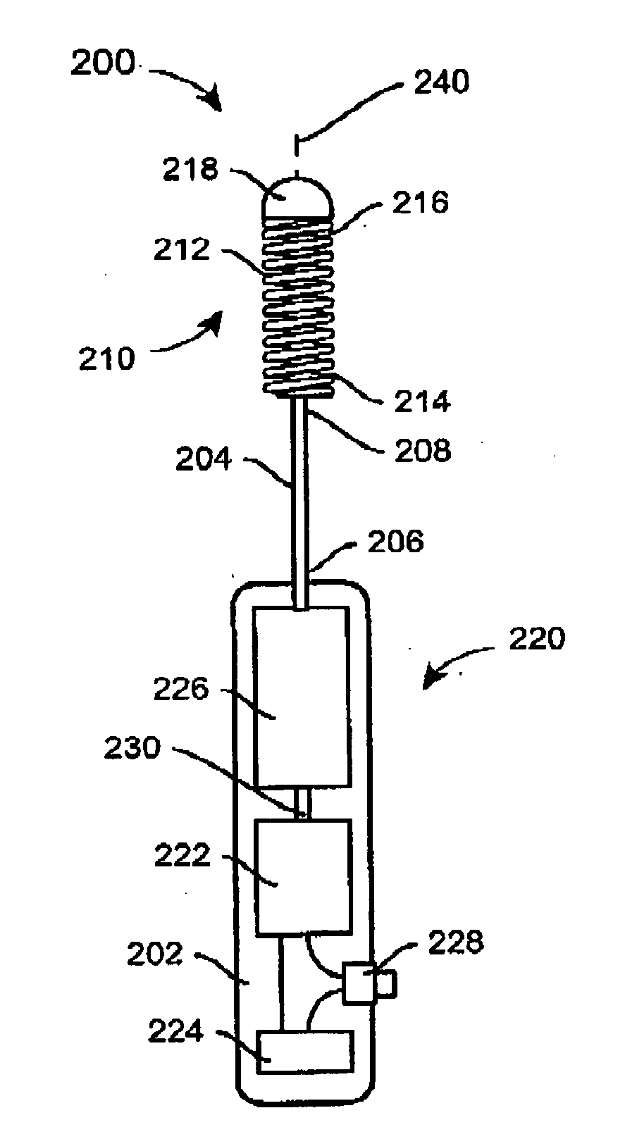
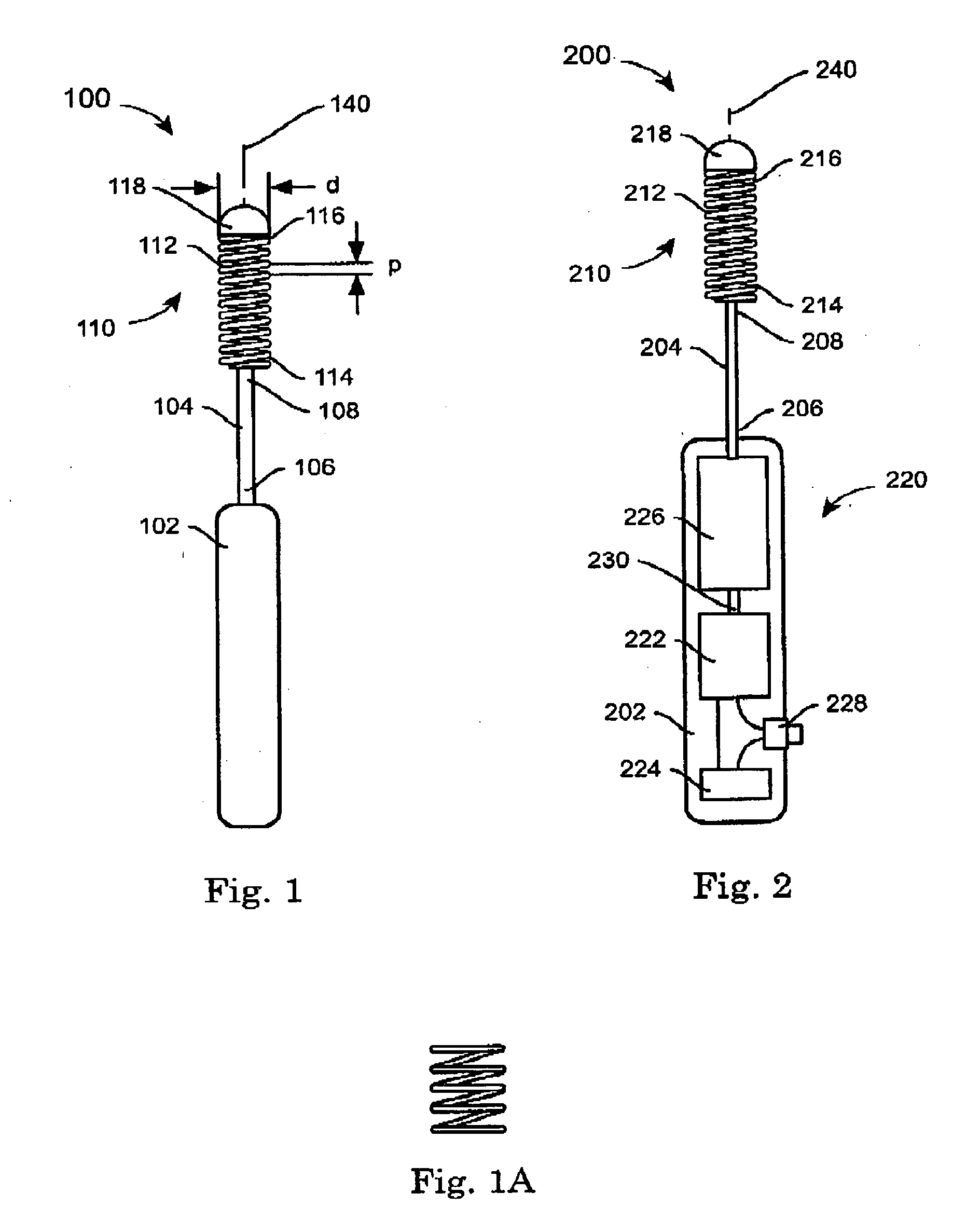
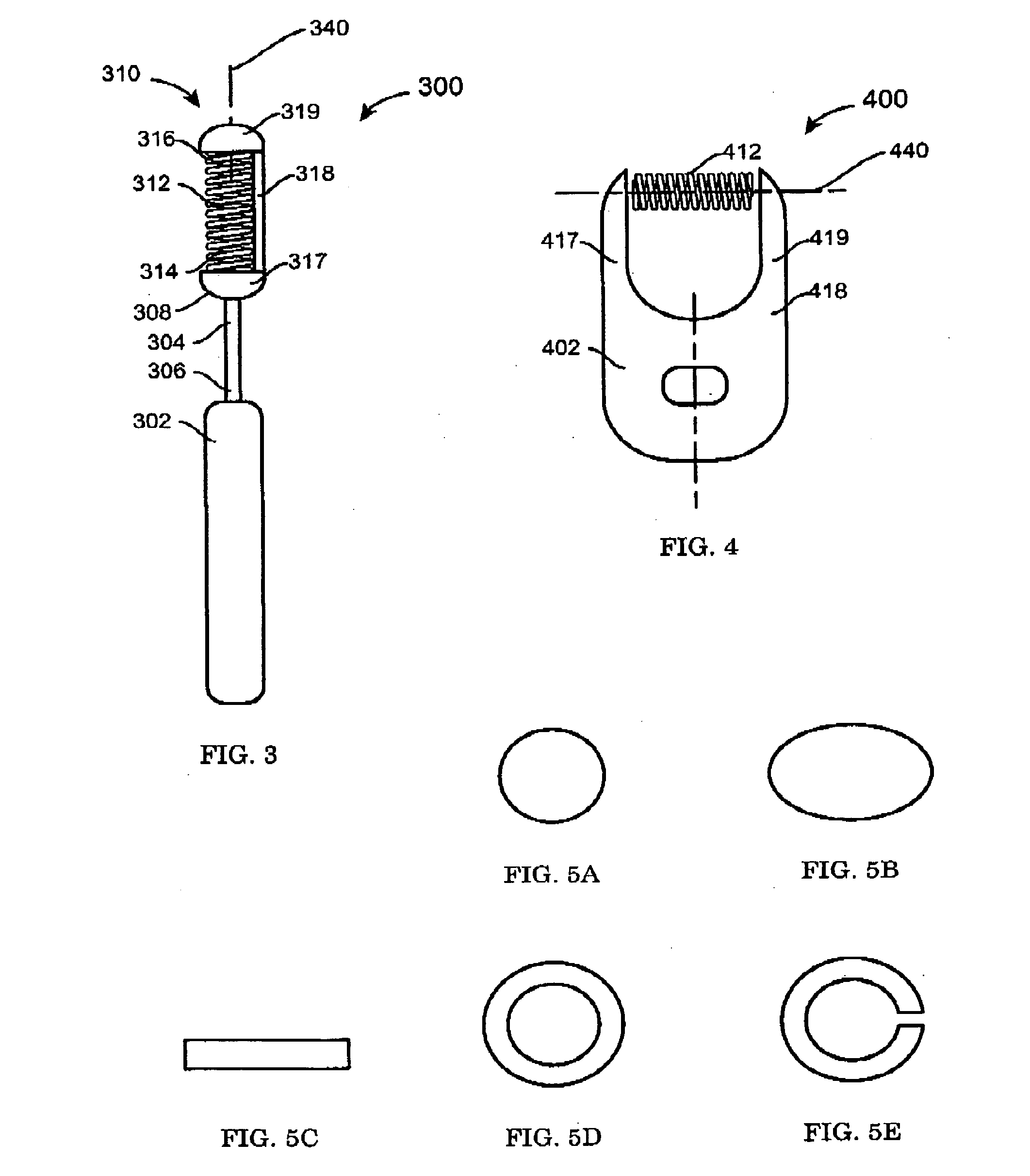
[0069]The present disclosure details a variety of cosmetic applicators having helical applicator heads and systems incorporating such applicators. FIGS. 1-4 introduce variants of the applicator generally, while FIGS. 5-36 illustrate various alternative embodiments of the helical applicator surfaces. FIGS. 37-45 illustrate various embodiments of an applicator with a helical applicator surface in combination with a source of cosmetic product and wipers to be used with the applicator. FIGS. 46 and 47 illustrate the applicators similar to those of FIGS. 1 and 2 in combination with a bottle or a holder. Throughout, a numbering convention has been adopted such that similar features of the various embodiments have been numbered in a similar manner.

[0070]Regardless of the embodiment, it is believed that use of a helical applicator surface may have one or more advantages over conventional applicator heads. It is believed that in certain circumstances the helical applicator head may subject l...


PUM


Abstract

An applicator system includes a handle and an applicator head coupled to the handle, the applicator head including at least one helical applicator surface, the at least one helical applicator surface disposed about a space. The applicator system also includes a source of product disposed axially within the at least one helical applicator surface.

Description

FIELD OF THE INVENTION[0001]The present disclosure is directed to an applicator system with a helical applicator surface and a source, such as a cosmetic applicator system with a helical applicator surface for use in applying cosmetic product from a source of cosmetic product.BACKGROUND OF THE INVENTION[0002]Various types of applicators are known in the art. Brushes or wands for applying product, such as mascara or a hair color product, to a target material, such as keratinous fibers like eyelashes and head hair, generally include an applicator head with a stem having a first end attached to a handle. The applicator head also includes one or more applicator elements coupled to the stem. The applicator elements may be in the form of bristles (such as in a twisted wire brush), molded fibers, molded surfaces, etc. In use, the applicator elements are loaded with product and applied to the target material, with the product being transferred from the outside of the applicator element to t...

Claims


Application Information

Patent Timeline
Patent Type & Authority Applications(United States)
IPC IPC(8): A45D40/26A46B11/00
CPCA45D40/265A45D2200/155A45D2200/157A45D2200/207A46B2200/106A46B9/028A46B11/002A46B13/02A46B2200/1053A46B9/021
Inventor WYATT, PETER JONATHANSANFORD, RONALD ALANWILSON, DAVID EDWARDRABE, THOMAS ELLIOTSIMONS, CAROLINE STONEYWATTERS, JOHN MICHAEL
Owner THE PROCTER & GAMBLE COMPANY
Why Eureka
Try Eureka