Radio frequency proximity sensor and sensor system

a radio frequency proximity and sensor technology, applied in the field of proximity sensors, can solve the problems of reduced effectiveness of mirrors at night, increased likelihood of vehicle incursion, and difficulty for the vehicle operator to see,

Inactive Publication Date: 2009-03-19
HONEYWELL INT INC
View PDF11 Cites 37 Cited by
  • Summary
  • Abstract
  • Description
  • Claims
  • Application Information

AI Technical Summary

Benefits of technology

[0007]In one embodiment, and by way of example only, a vehicle blind spot sensing system includes a plurality of blind spot detectors mounted on a vehicle and a processor. Each blind spot detector has a detection region around the vehicle, and each blind spot detector is operable to transmit three or more radio frequency (RF) signals of different frequencies, receive reflected RF signals, and supply intermediate frequency (IF) signals. Each IF signal is representative of one of the reflected RF signals, and each reflected RF signal corresponds to a transmitted RF signal that was reflected by a moving object disposed within its detection region. The processor is coupled to receive the IF signals supplied from at least one blind spot detector and is operable, upon receipt of the IF signals, to determine whether a moving object is within the detection region of the at least one blind spot detector.
[0008]In another exemplary embodiment, a proximity sensor includes a radio frequency (RF) sensor, a pulse generator, a plurality of detection channels, and a processor. The RF sensor is coupled to receive a frequency control signal and is operable, in response thereto, to generate and transmit a plurality of RF signals of different frequencies. The RF sensor is further operable to receive reflected RF signals and to supply intermediate frequency (IF) signals. Each IF signal is representative of one of the reflected RF signals, and each reflected RF signal corresponds to a transmitted RF signal that was reflected by an object moving in a direction. The pulse generator is coupled to the RF sensor and is operable to supply the frequency control signal thereto. Each detection channel is coupled to receive one of the IF signals supplied by the RF sensor and is operable to supply a digital signal representative of the IF signal. The processor is coupled to receive the digital signal supplied from each of the detection channels and is operable, upon receipt thereof, to determine a distance to, and the direction of, the moving object that reflected the transmitted RF signal.
[0009]In yet another exemplary embodiment, a method of detecting the presence of and distance to an object moving in a movement direction includes transmitting three or more radio frequency (RF) signals of different frequencies. Reflected RF signals that correspond to the transmitted RF signals that were reflected by a moving object are received. The relative phase angles between two or more sets of reflected RF signals are determined, and the distance to and the movement direction of the object is determined from the determined relative phase angles.

Problems solved by technology

Many automotive vehicles are configured such that there are regions around the vehicle where objects, which may be near the vehicle, may be difficult for the vehicle operator to see.
No matter the specific location and size of a specific vehicle's blind spots, the blind spots may increase the likelihood for vehicle incursion into an object that is in a vehicle's blind spot.
For example, mirrors may exhibit reduced effectiveness at night and under adverse weather conditions.
Camera-based systems can be relatively complex and expensive, relying on the use of a video camera and video monitor.
Further, a video monitor can be distracting and / or can present a relatively complex image that may be difficult for a vehicle operator to interpret and such monitors can be distracting.
Moreover, camera-based systems can also exhibit reduced effectiveness at night and under adverse weather conditions.
Radar based systems that use traditional technology can be relatively complex and expensive.
In addition, the above-described radar based phase detection system exhibits ambiguity for phase differences greater than 180-degrees, and the radar based systems on other vehicles can cause interference with each other, thereby reducing effectiveness and reliability.

Method used


Image

  • Radio frequency proximity sensor and sensor system
  • Radio frequency proximity sensor and sensor system
  • Radio frequency proximity sensor and sensor system

Examples


Embodiment Construction

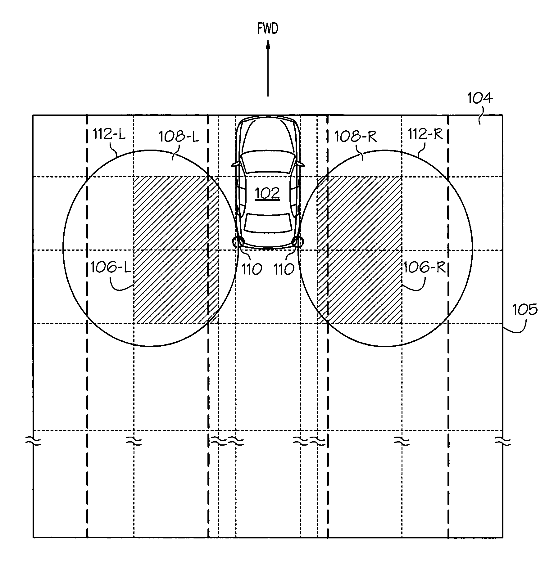
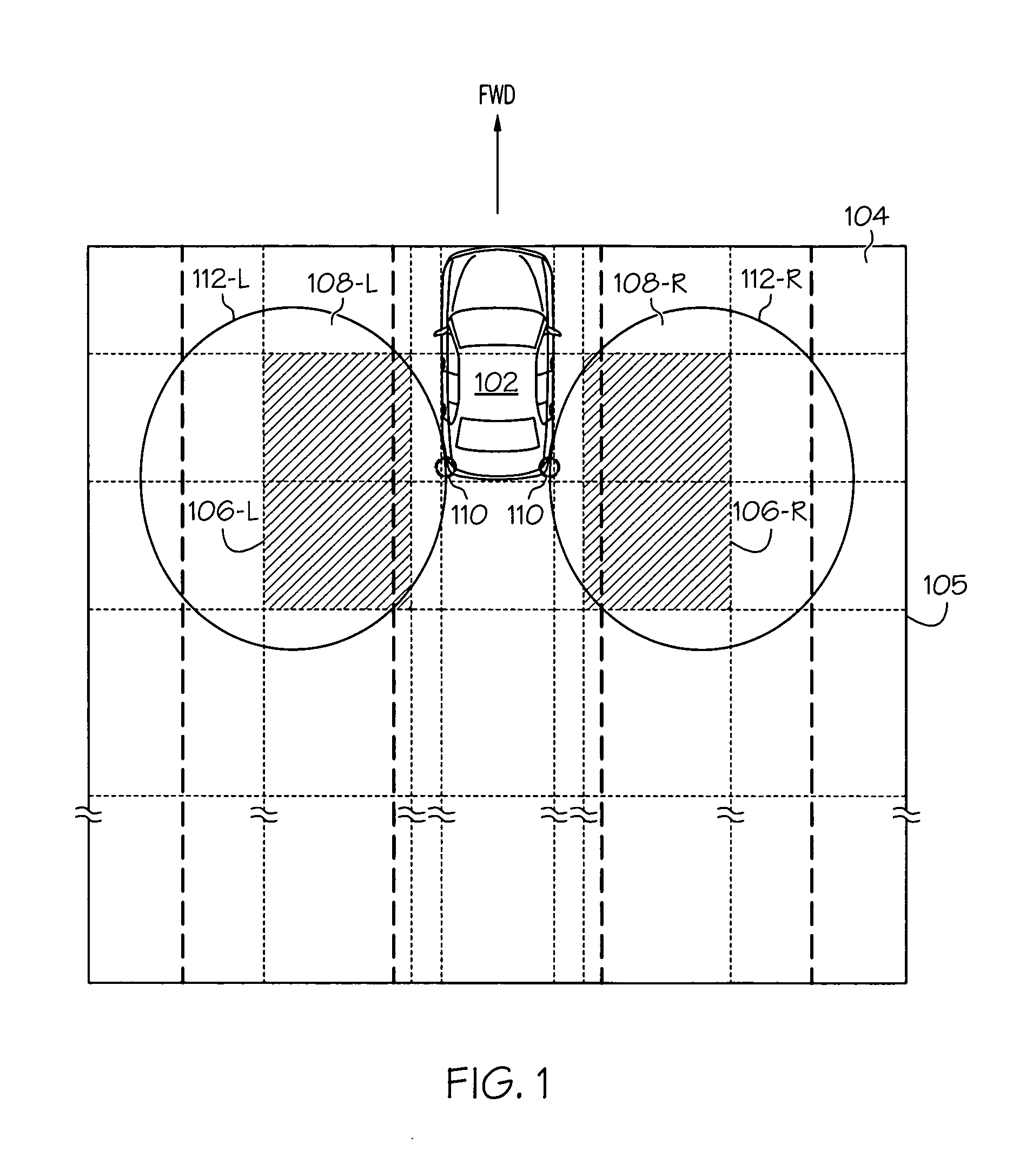
[0019]The following detailed description is merely exemplary in nature and is not intended to limit the invention or the application and uses of the invention. Furthermore, there is no intention to be bound by any theory presented in the preceding background or the following detailed description. In this regard, although embodiments of an inventive sensor are described as being implemented in an automobile blind spot detection system, it will be appreciated that the sensor may be implemented in numerous other systems and environments. For example, the sensor may be used to detect the presence of objects near residential, commercial, governmental, or military buildings or other facilities. Moreover, as used herein the term “object” or “objects” may refer to both animate and inanimate objects.

[0020]Referring now to FIG. 1, an exemplary vehicle 102 is depicted on a driving surface 104. Various regions are also graphically depicted in FIG. 1. These regions include a plurality of operato...


PUM


Abstract

A proximity sensor may be used as part of a vehicle blind spot detection system. The sensor is configured to transmit multiple radio frequency (RF) signals of different frequencies, receive reflected RF signals, and supply intermediate frequency (IF) signals. Each IF signal is representative of one of the reflected RF signals, and each reflected RF signal corresponds to a transmitted RF signal that was reflected by an object within the sensor detection region. The sensor uses the IF signals to determine whether an object is within its detection region and its movement direction.

Description

CROSS-REFERENCE TO RELATED APPLICATION[0001]This application claims the benefit of U.S. Provisional Application Ser. No. 60 / 972,485, filed Sep. 14, 2007.TECHNICAL FIELD[0002]The present invention generally relates to proximity sensors and, more particularly, to a radio frequency (RF) proximity sensor that may be used for sensing objects in a vehicle blind spot.BACKGROUND[0003]Many automotive vehicles are configured such that there are regions around the vehicle where objects, which may be near the vehicle, may be difficult for the vehicle operator to see. These regions are typically referred to as “blind spots.” The specific locations of a vehicle's blind spots may vary depending, for example, on vehicle model and vehicle operator. Typical blind spot locations, however, include regions to the left and right of the vehicle operator that extend toward the rear of the vehicle, and the rear of the vehicle. No matter the specific location and size of a specific vehicle's blind spots, the...

Claims


Application Information

Patent Timeline
Patent Type & Authority Applications(United States)
IPC IPC(8): B60Q1/00
CPCB60Q9/004G01S2013/9332G01S13/584G01S13/348G01S2013/9315
Inventor WU, XIAODONGVACANTI, DAVID C.LE, QUA VAN
Owner HONEYWELL INT INC
Why Eureka
Try Eureka