Socket connector having leading-and-positioning arrangement within a passageway and method for mating with the same

Inactive Publication Date: 2009-03-19
HON HAI PRECISION IND CO LTD
View PDF2 Cites 0 Cited by
  • Summary
  • Abstract
  • Description
  • Claims
  • Application Information

AI Technical Summary

Benefits of technology

[0006]Accordingly, an object of the present invention is to provide an electrical connector with an easily interconnection between the connector and a mating pin.

Problems solved by technology

However, the opposing contacting arms 234 may not provide a steadily connecting effect and the configuration of the terminals 218 are complex and not advantage for manufacturing.

Method used


Image

  • Socket connector having leading-and-positioning arrangement within a passageway and method for mating with the same
  • Socket connector having leading-and-positioning arrangement within a passageway and method for mating with the same
  • Socket connector having leading-and-positioning arrangement within a passageway and method for mating with the same

Examples


Embodiment Construction

[0017]Reference will now be made to the drawing figures to describe a preferred embodiment of the present invention in detail.

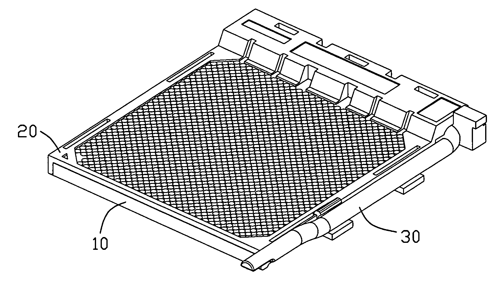
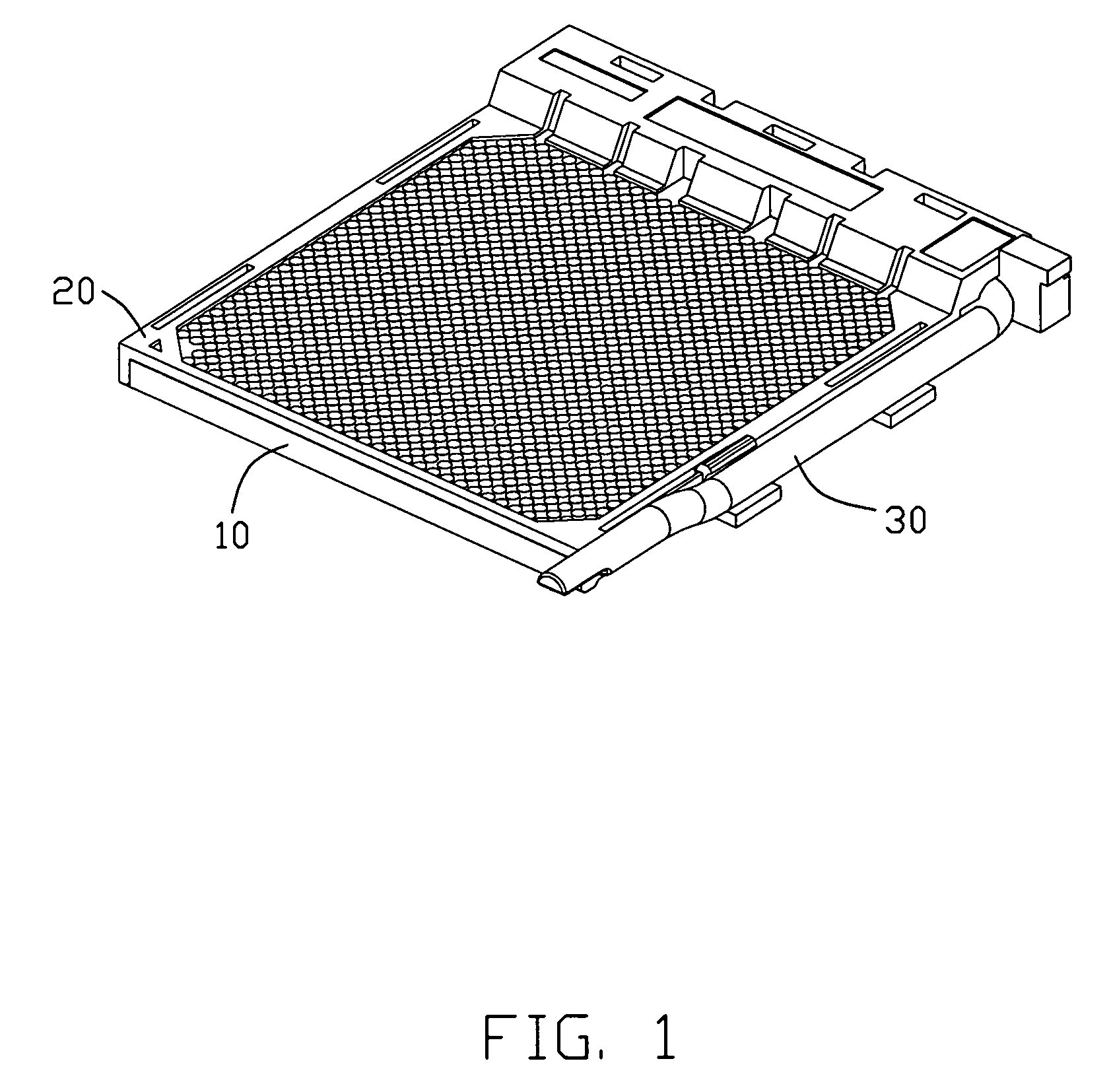
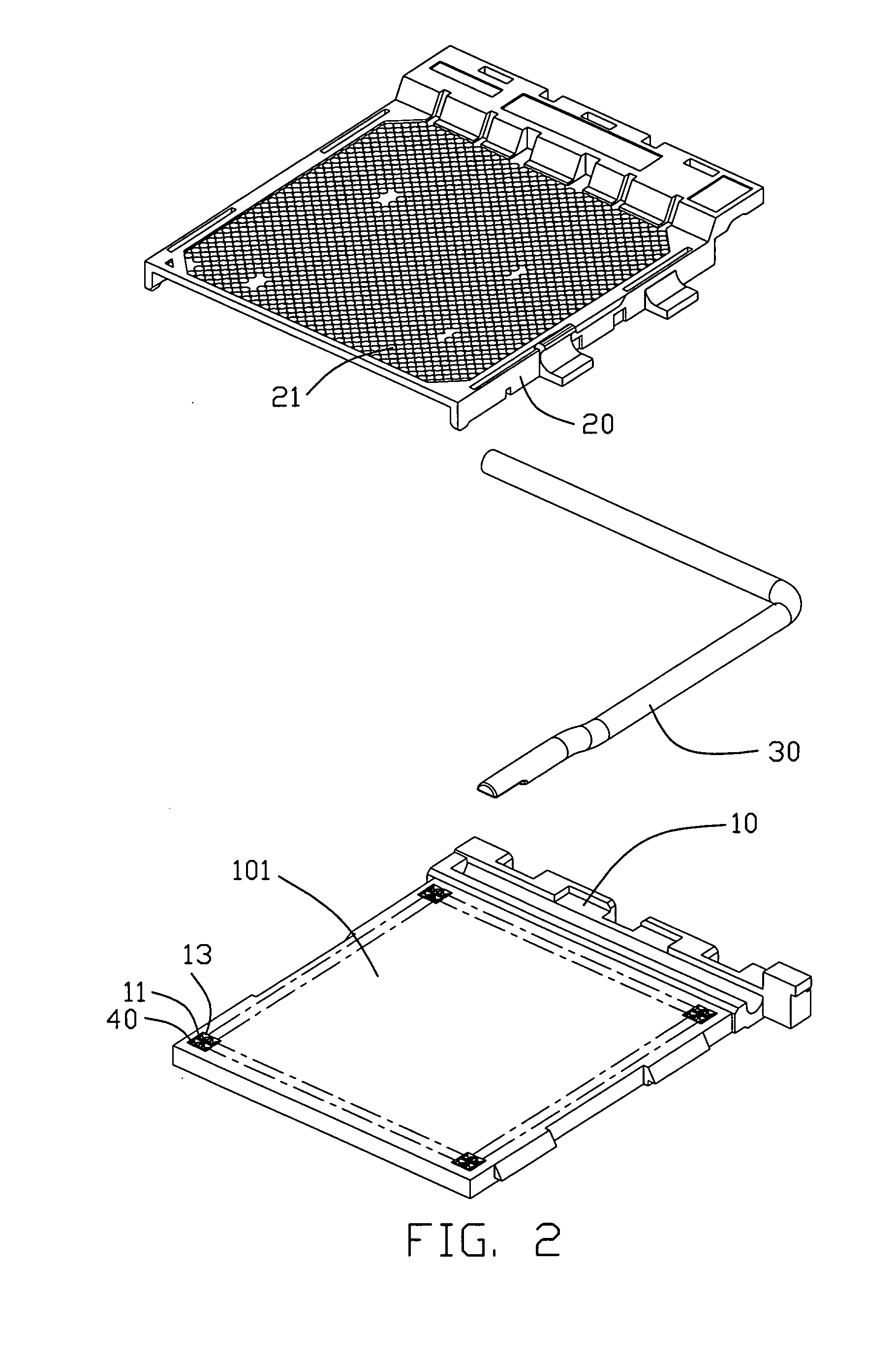
[0018]Referring to FIGS. 1 and 2, an electrical connector 100 in accordance with the present invention is provided and comprises an insulating base 10 mounting a plurality of terminals 40 thereon, a cover 20 movably assembled on the insulating base 10 and a level 30 actuating the cover 20 to slide on the insulating base 10. FIG. 5 shows engagement of the electrical connector 100 with a mating material 70, such as pins of an IC package in this embodiment.

[0019]Referring to FIGS. 2 and 3, the insulating base 10 is in a rectangular shape and defines a plurality of receiving passageways 11 therein running through in an up-to-down direction. Each receiving passageway 11 is enclosed by four side walls 13. For easily description, the receiving passageway 11 together with the side walls 13 is named as a receiving unit hereafter.

[0020]As shown in FIG. 3, the receiving...


PUM


Abstract

An electrical connector (100) includes an insulating base (10) defining therein a plurality of receiving units (11) each surrounded by sidewalls (13). A cover (20) is moveably disposed on the insulating base (10) and includes a plurality of apertures (21) each aligned with the receiving units (11). A driving mechanism (30) is disposed on the base to drive the cover (20) to move along the base (10). Each receiving unit (11) includes a leading-and-positioning arrangement (14) extending from an inner sidewall (13b) thereof, and dividing the receiving unit into a first space (110) and a second space (111). A plurality of terminals (40) is received in said receiving units (11), each comprises a contacting portion (42) projecting into the second space (111) of the receiving unit (11).

Description

BACKGROUND OF THE INVENTION[0001]1. Field of the Invention[0002]The present invention relates to a socket connector, and more particularly, to a socket connector having leading-and-positioning arrangement within the passageway facilitating easy and reliable interconnection between a pin leg from a CPU and a contact arranged within the passageway.[0003]2. Description of the Prior Art[0004]TW patent No. 444944 issued to Mchugh on Jul. 1, 2001, discloses a conventional socket connector as shown in FIG. 9. The connector has an insulating housing 12′ with a plurality of terminals 218′ mounted therein. The insulating housing 12′ defines a plurality of receiving grooves 16′ therein and each receiving groove 16′ defines a pair of retaining passageways 26 at opposite sides thereof. Each terminal 218 comprises a mounting portion 222′ retained in the passageway 26, a pair of connecting portions 232′ extending from opposite edges of the mounting portion 222′ and perpendicular to the mounting po...

Claims


Application Information

Patent Timeline
IPC IPC(8): H01R13/62
CPCH05K7/1007H01R13/193
Inventor ZHANG, JIE-FENG
Owner HON HAI PRECISION IND CO LTD
Why Eureka
Try Eureka