Photovoltaic power generation system and photovoltaic power generation system control method

Inactive Publication Date: 2009-06-25
SHARP KK
View PDF0 Cites 44 Cited by
  • Summary
  • Abstract
  • Description
  • Claims
  • Application Information

AI Technical Summary

Benefits of technology

[0040]In accordance with the photovoltaic power generation system and photovoltaic power generation system control method of the present invention, generator unit groups, which are formed by arrangement of multiple photovoltaic power generator units and a unit group power collection control section, which collects the electrical power generated by the generator unit groups and controls the tracking drive section, are used to detect the power generation state of the photovoltaic power generator units, as a result of which a decrease in the electrical power generated by the photovoltaic power generator units (photovoltaic power generation system) can be prevented by correcting the power generation malfunctions of the photovoltaic power generator units exhibiting power generation malfunctions.
[0041]Moreover, in accordance with the photovoltaic power generation system and photovoltaic power generation system control method of the present invention, power generation malfunctions can be readily detected and corrected in real time, as a result of which a photovoltaic power generation system can be produced that offers easy interconnection to electric power systems and is safe and stable.
[0042]Moreover, in accordance with the photovoltaic power generation system and photovoltaic power generation system control method according to the present invention, the power generation state of the generator unit groups is detected for multiple generator unit

Problems solved by technology

The only difference of concentrator-type modules is that they are constructed to collect sunlight with lenses and irradiate ph

Method used


Image

  • Photovoltaic power generation system and photovoltaic power generation system control method
  • Photovoltaic power generation system and photovoltaic power generation system control method
  • Photovoltaic power generation system and photovoltaic power generation system control method

Examples


Example

Embodiment 1

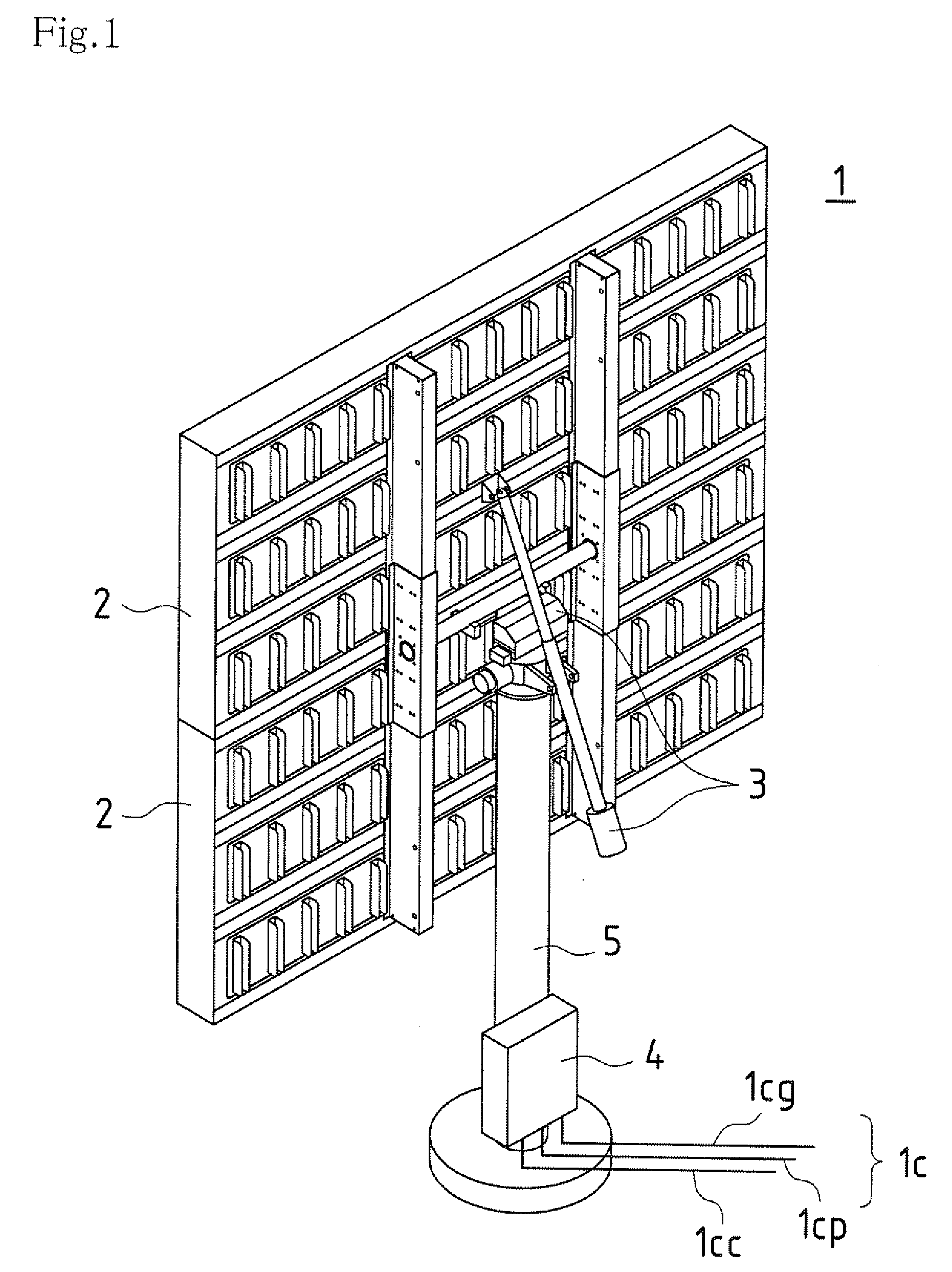
[0103]FIG. 1 is a perspective view illustrating the external appearance of a photovoltaic power generator unit used in a photovoltaic power generation system according to Embodiment 1 of the present invention.

[0104]The main components of a photovoltaic power generator unit 1 are solar cell modules 2 and a tracking drive section 3. In other words, the photovoltaic power generator unit 1 is designed as a tracking type solar cell module. Moreover, the solar cell modules 2 have multiple photovoltaic cells installed therein to form basic functional sections for photovoltaic power generation. FIG. 1 illustrates a state, in which the solar cell modules 2 are viewed from the back. Although the solar cell modules 2 are preferably of the concentrator type, they are not limited thereto. If they are not of the concentrator type, the only difference is that the angular tolerance of the tracking angle shift is larger while the rest of the components are the same as in the concentrator...

Example

Embodiment 2

[0131]The present embodiment relates to an exemplary process flow describing application of control to the drive of the photovoltaic power generator units 1 in the photovoltaic power generation system 10 according to Embodiment 1.

[0132]FIG. 7 is a flow chart illustrating an exemplary basic process flow of drive control in a photovoltaic power generation system (photovoltaic power generator unit) without power generation state detection.

[0133]It should be noted that basic control over the process flow (photovoltaic power generation system control method) used herein is effected by the unit group power collection control sections 12 with respect to the photovoltaic power generator units 1 situated in the generator unit group 11. In other words, it can be carried out using software pre-installed in the unit group power collection control sections 12. Moreover, it is adapted to be suitably linked to the management PC 18 as the occasion demands.

[0134]Step S501:

[0135]After sun...

Example

Embodiment 3

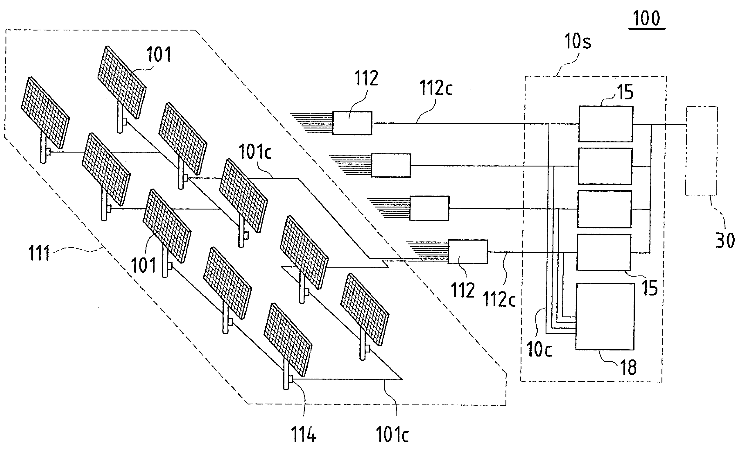
[0259]FIG. 11 is a conceptual block diagram conceptually illustrating an exemplary configuration of a photovoltaic power generation system according to Embodiment 3 of the present invention.

[0260]In Embodiment 1 and Embodiment 2, the generator unit groups 11 situated in the photovoltaic power generation system 10 are adapted for controlling the photovoltaic power generator units 1 using the respective corresponding unit group power collection control sections 12. In such a case, the photovoltaic power generator units 1 controlled by the unit group power collection control sections 12 are imparted tracking drive using the same control method and, as a result, the respective amounts of electrical power generated by the multiple generator unit groups 11 become substantially equal.

[0261]In other words, it may be impossible to determine the difference in generated electrical power between the generator unit groups 11 (unit group power collection sections 12) simply by compari...


PUM


Abstract

A photovoltaic power generation system, wherein electrical power generated by multiple photovoltaic power generator units is gathered in a single unit group power collection control section and, in addition, supplied (transferred) to a single power converter corresponding to a single unit group power collection control section. The photovoltaic power generation system comprises generator unit groups formed by arrangement of multiple photovoltaic power generator units and unit group power collection control sections, which are connected with the photovoltaic power generator units through unit cables, and collect and control the electric power generated by the photovoltaic power generator units.

Description

TECHNICAL FIELD[0001]The present invention relates to a photovoltaic power generation system formed by arrangement of multiple photovoltaic power generator units having solar cell modules and a tracking drive section, as well as to a control method for a photovoltaic power generation system.BACKGROUND ART[0002]In recent years, the development of clean energy has become desirable due to global environmental concerns, such as the problems of energy resource depletion and increased CO2 levels in the atmosphere, etc. In particular, photovoltaic power generation (photovoltaic power generation systems), which uses solar cells, has been developed and put to practical use as a new energy source.[0003]For photovoltaic power generation systems, cost reduction would be desirable in terms of achieving wider adoption and a photovoltaic power generation system that improves the amount of generated electrical power and decreases the per-unit cost of the generated electrical power by comprising a t...

Claims


Application Information

Patent Timeline
IPC IPC(8): H01L31/042F24S50/20
CPCF24J2/38F24J2/523H02S20/00Y02E10/47Y02E10/50F24J2/542H02S20/32H02S20/10F24S50/20F24S25/10F24S30/452
Inventor MORIMOTO, KEIJI
Owner SHARP KK
Why Eureka
Try Eureka