Shin Guard

a technology for shins and shins, applied in the field of shin guards, can solve the problems of hardly possible bandages and consequently slippage of shield elements, and achieve the effect of stable positioning of shield elements on the shins

Inactive Publication Date: 2009-03-26
S1 SPORT INT LTD
View PDF11 Cites 13 Cited by
  • Summary
  • Abstract
  • Description
  • Claims
  • Application Information

AI Technical Summary

Benefits of technology

[0003]The present invention is based on the problem of creating a new shin guard of the kind

Problems solved by technology

Therefore, under normal circumstances, it is hardly possible

Method used


Image

  • Shin Guard
  • Shin Guard
  • Shin Guard

Examples


Embodiment Construction

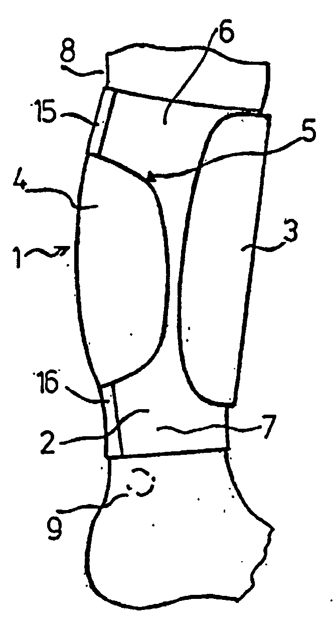
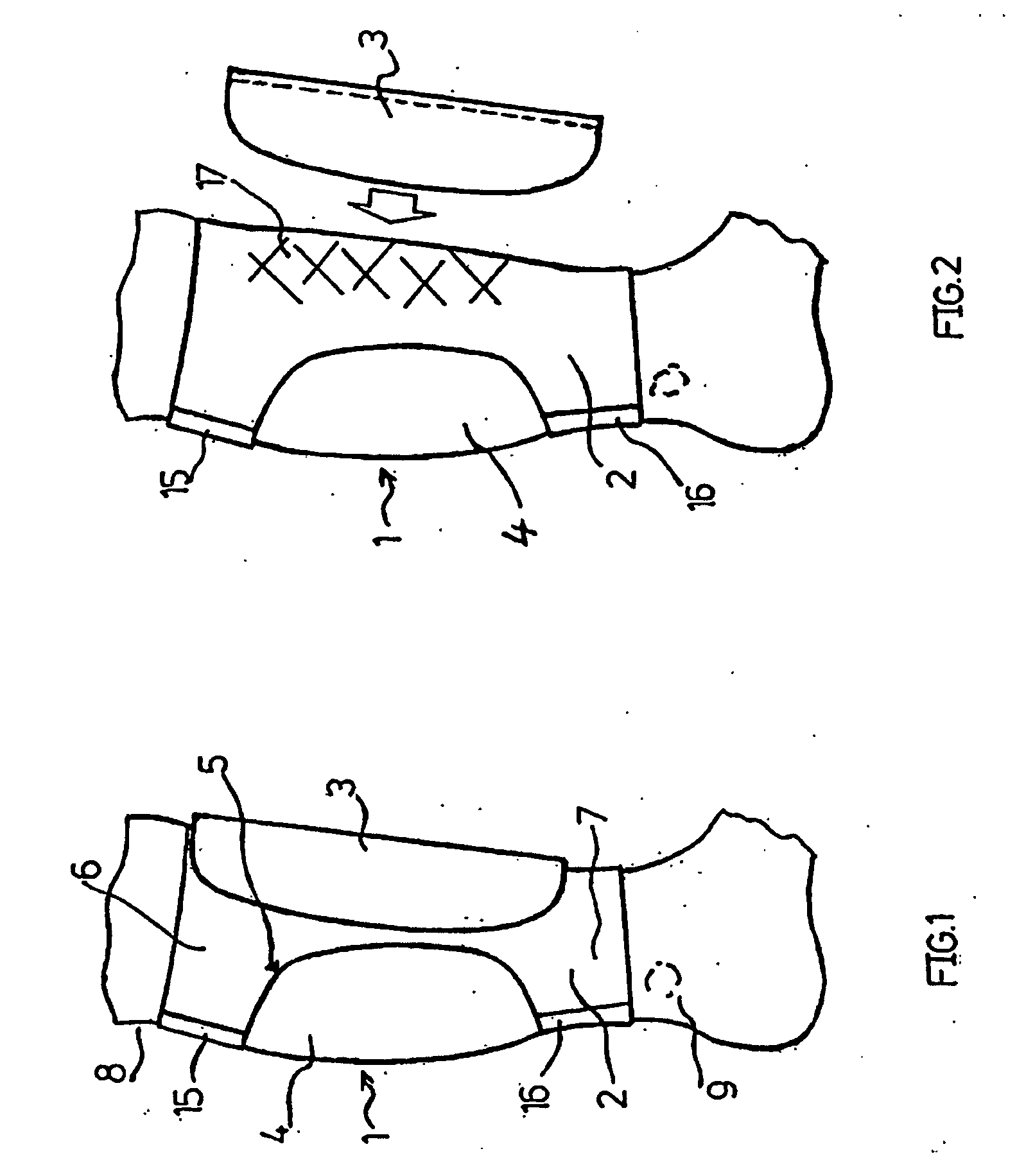
[0019]A shin guard for a soccer player, which is to be worn under the player's socks, has a bandage (2) that can be attached to the lower leg (1) and combined by way of a Velcro® hook and eye fabric fastener with a rigid shield element (3) that is intended to be positioned in front of the shin.

[0020]The bandage (2), manufactured from an elastic textile material, possesses an opening (5) that leaves the calf (4) largely uncovered. The connecting sections (6) and (7) remaining above and below the opening each extend across an area of the lower leg in which changes to the cross-section of the lower leg as a result of calf-muscle activity are minimal.

[0021]As can be seen in FIG. 1, the bandage (2) extends upwards to near the hollow of the knee (8), and downwards to near the ankle (9).

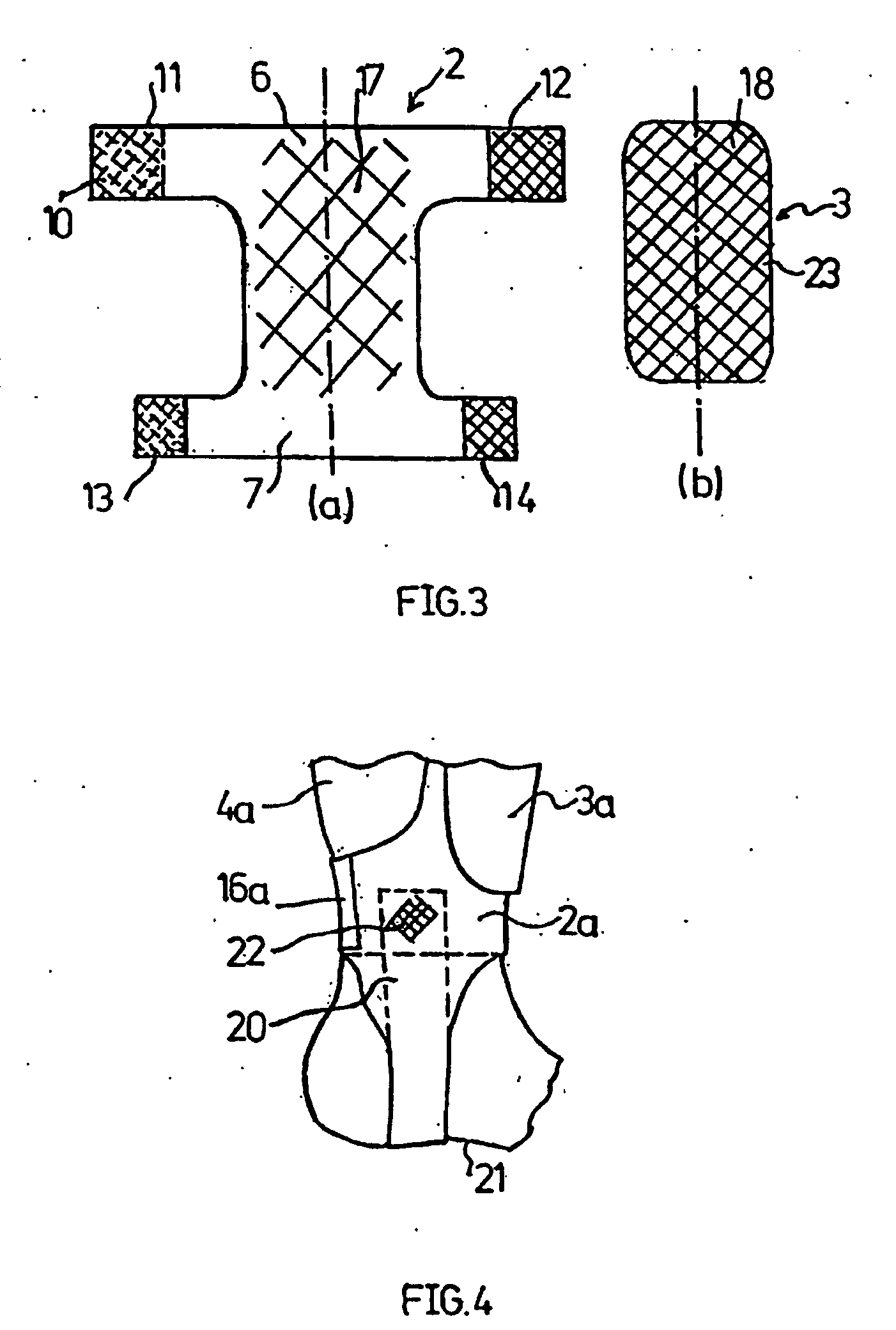
[0022]In accordance with FIG. 3a, which shows the bandage (2) detached from the lower leg and spread out in one plane, the connecting section (6) comprises the flaps (11) and (12), and the connecting sectio...


PUM


Abstract

The invention relates to a shin guard, in particular for footballers, having a stiff shield element (3) arranged in front of the shin, and having means of fastening the shield element (3) on the lower leg (1). According to the invention, the fastening means have a strapping device (2) running around the lower leg (1), and the shield element (3) is connected to the strapping device (2) over much of its inner surface (18), which is directed towards the shin.

Description

FIELD OF INVENTION[0001]The invention concerns a shin guard, in particular for soccer players, having a rigid shield element arranged in front of the shin, and having means of fastening the shield element on the lower leg.BACKGROUND OF THE INVENTION[0002]The fastening means on conventional shin guards for soccer players comprise flaps whose ends can be joined together at the back of the lower leg, and whose other ends are attached to the shield element at the latter's edge. Forces acting on the shield are transmitted in their entirety to the flaps via the joints, which causes not only the flaps, but also the shield element to slip slightly during play and is extremely unpleasant for the player.BRIEF SUMMARY OF THE INVENTION[0003]The present invention is based on the problem of creating a new shin guard of the kind mentioned above, which ensures a more stable positioning of the shield element on the shin.[0004]According to the present invention, this problem is solved by a shin guard...

Claims


Application Information

Patent Timeline
IPC IPC(8): A41D13/00A61F13/06A61F5/37
CPCA63B71/1225A63B2209/10A63B2071/1266A63B2071/1258A41D13/00A41D13/015A41D31/00A63B71/12A63B71/14
Inventor SCHEFFER, HARALD
Owner S1 SPORT INT LTD
Why Eureka
Try Eureka