Electric steering lock device

a technology of steering lock and electric steering, which is applied in the direction of mechanical control devices, anti-theft devices, instruments, etc., can solve the problem that the vehicle cannot be maneuvered

Inactive Publication Date: 2009-04-02
ALPHA
View PDF14 Cites 15 Cited by
  • Summary
  • Abstract
  • Description
  • Claims
  • Application Information

AI Technical Summary

Benefits of technology

[0017]By the configuration as described above, the lever member can be protected from a destructiv

Problems solved by technology

However, the conventional electric steering lock device 100 had a risk of a so-called soft attack where a small through hole is opened in the cover for example of the electric steering lock device 100 and the lock member 103 is directly operated through this hole to mo

Method used


Image

  • Electric steering lock device
  • Electric steering lock device
  • Electric steering lock device

Examples


Embodiment Construction

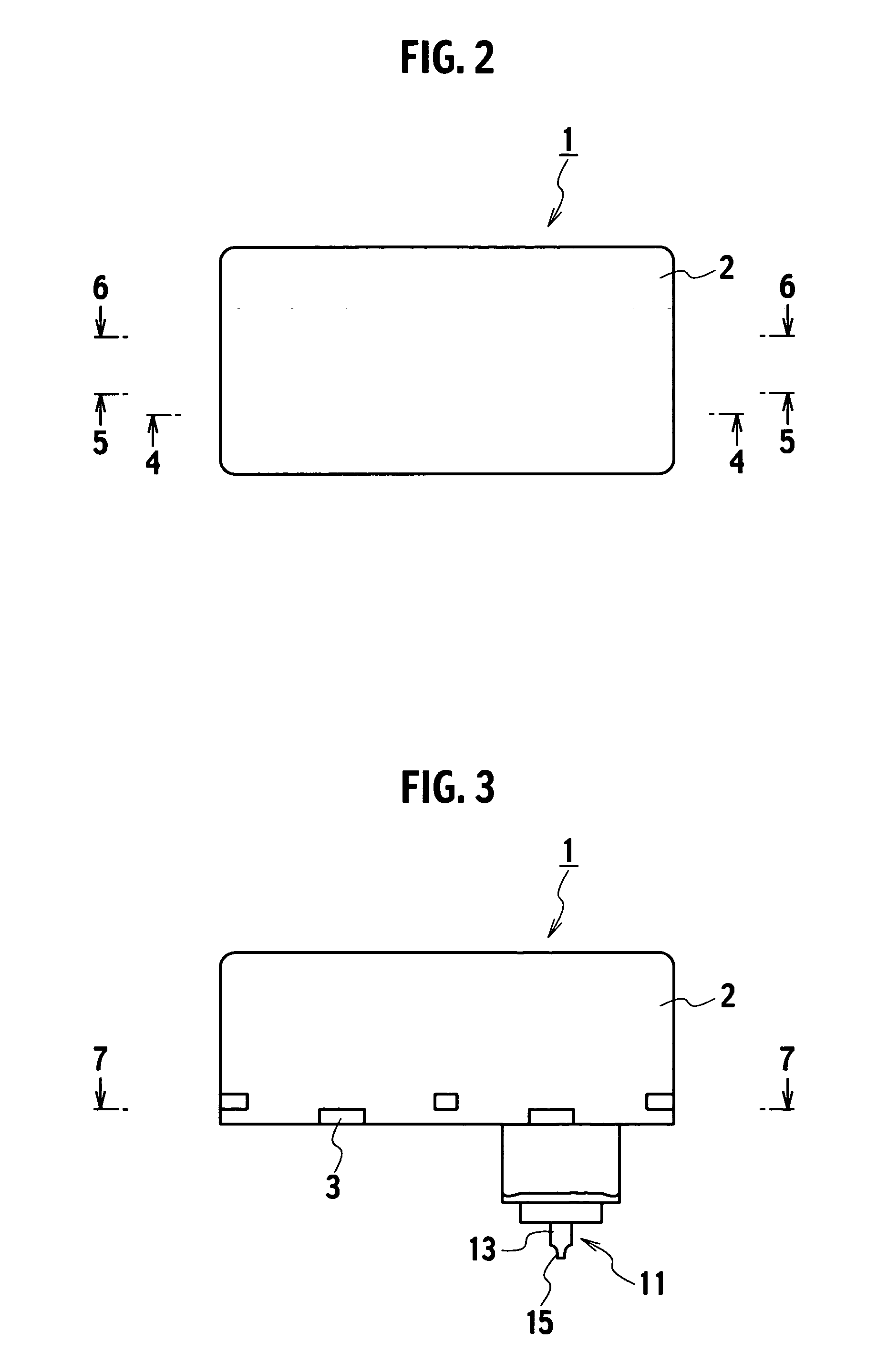
[0030]The following section will describe one embodiment of the present invention with reference to the drawings. FIG. 2 to FIG. 10 illustrate one embodiment of the present invention.

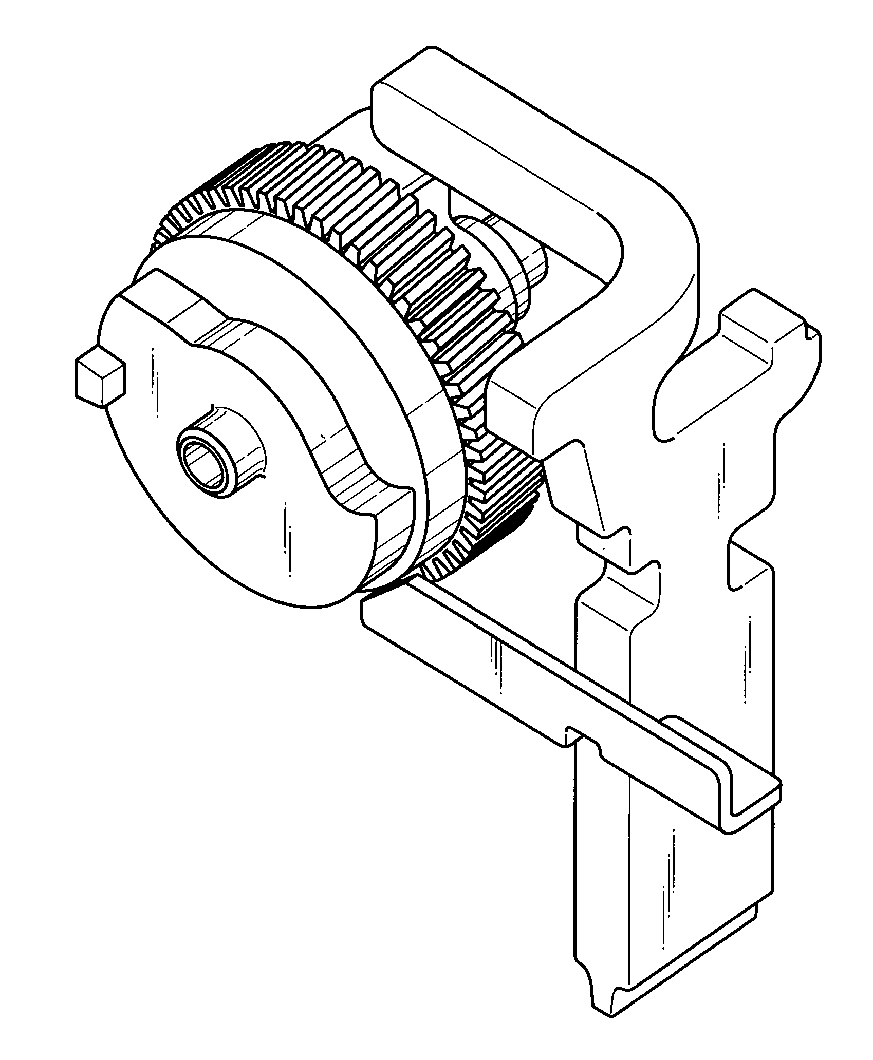
[0031]As shown in FIG. 2 to FIG. 10, the electric steering lock device 1 includes, as main configuration parts, a cover 2 and a housing 3 that are assembled to each other to form a part accommodation room at the interior thereof; a drive unit housing 4 and a drive unit cover 5 that are accommodated in the part accommodation room and that further form a drive unit room at the interior thereof; a motor 6 that is a driving source provided in the drive unit room; a worm gear 7 that is fixed to a rotation axis 6a of the motor 6; a rotating body (worm wheel) 8 that is meshed with the worm gear 7 and that is rotatably supported in the drive unit room; a first cam section 9 that is integrated with one face of the worm wheel 8; a second cam section 10 that is integrated with the other face of the worm wheel 8; a...


PUM


Abstract

An electric steering lock device of the invention includes: a rotating body (worm wheel) that is driven by a motor to rotate in an unlocking direction and a locking direction; a first cam section and a second cam section provided in the worm wheel; a lock member that follows the first cam section to be displaced between a lock position and an unlock position; and a lever member that follows the second cam section and that is positioned, when the lock member is positioned at the unlock position, at a waiting position at which the lock member is allowed to move and that is positioned, when the lock member is moved to the lock position, at a retention position at which the lock member is blocked from moving to the unlock position.

Description

BACKGROUND OF THE INVENTION[0001]1. Field of the Invention[0002]The present invention relates to an electric steering lock device that locks the rotation of a steering shaft of a vehicle.[0003]2. Description of the Related Art[0004]This type of conventional electric steering lock device is disclosed in Patent Publication 1. As shown in FIG. 1, this electric steering lock device 100 includes: a lock member 103 that is urged by a coil spring 101 in a direction of a steering shaft 102 of a vehicle and that can be engaged with the steering shaft 102; a rotating body 106 that is connected to and driven by the motor 104 and that has a cam groove 105; a pin 107 that is moved along the cam groove 105 by the rotation of the rotating body 106 to move the lock member 103 between the lock position and the unlock position; and a lock stopper 109 that is moved in conjunction with the operation of the pin 107 and that is urged by a coil spring 108 in a direction of the lock member 103. When the lo...

Claims


Application Information

Patent Timeline
IPC IPC(8): B60R25/02B60R25/0215
CPCB60R25/02153Y10T70/5664Y10T70/5956B60R25/021E05B77/44E05B81/24
Inventor SUGIMOTO, KOICHIRO
Owner ALPHA
Why Eureka
Try Eureka