
Cutter for cutting a coiled band

a cutter and coiled technology, applied in the field of cutters, can solve the problems of time-consuming and inconvenient, hand injury,

Inactive Publication Date: 2009-04-02
YU CHEN HSIU MAN
View PDF16 Cites 12 Cited by
  • Summary
  • Abstract
  • Description
  • Claims
  • Application Information

AI Technical Summary

Benefits of technology

"The invention is a cutter for cutting a coiled band. It has a main body, a cutting base, and a knife unit. The cutting base is installed on the main body and has a rectangular frame with a cutting groove and sliding plates. The sliding plates have sliding rails that connect with a pressing rod. The front end of the coiled band passes through the frame while the pressing rod is lifted up, and then the pressing rod is released to press on the coiled band. This allows the knife unit to pivot and securely cut the coiled band flatly. The technical effect of this invention is to provide a precise and efficient tool for cutting coiled bands."

Problems solved by technology

It is always time-consuming and inconvenient, especially for cutting a large size.
Moreover, hands are possible to be hurt.

Method used


Image

  • Cutter for cutting a coiled band
  • Cutter for cutting a coiled band
  • Cutter for cutting a coiled band

Examples


Embodiment Construction

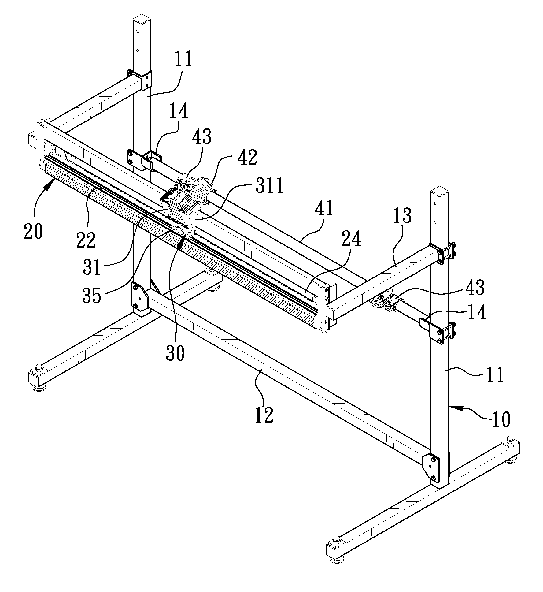
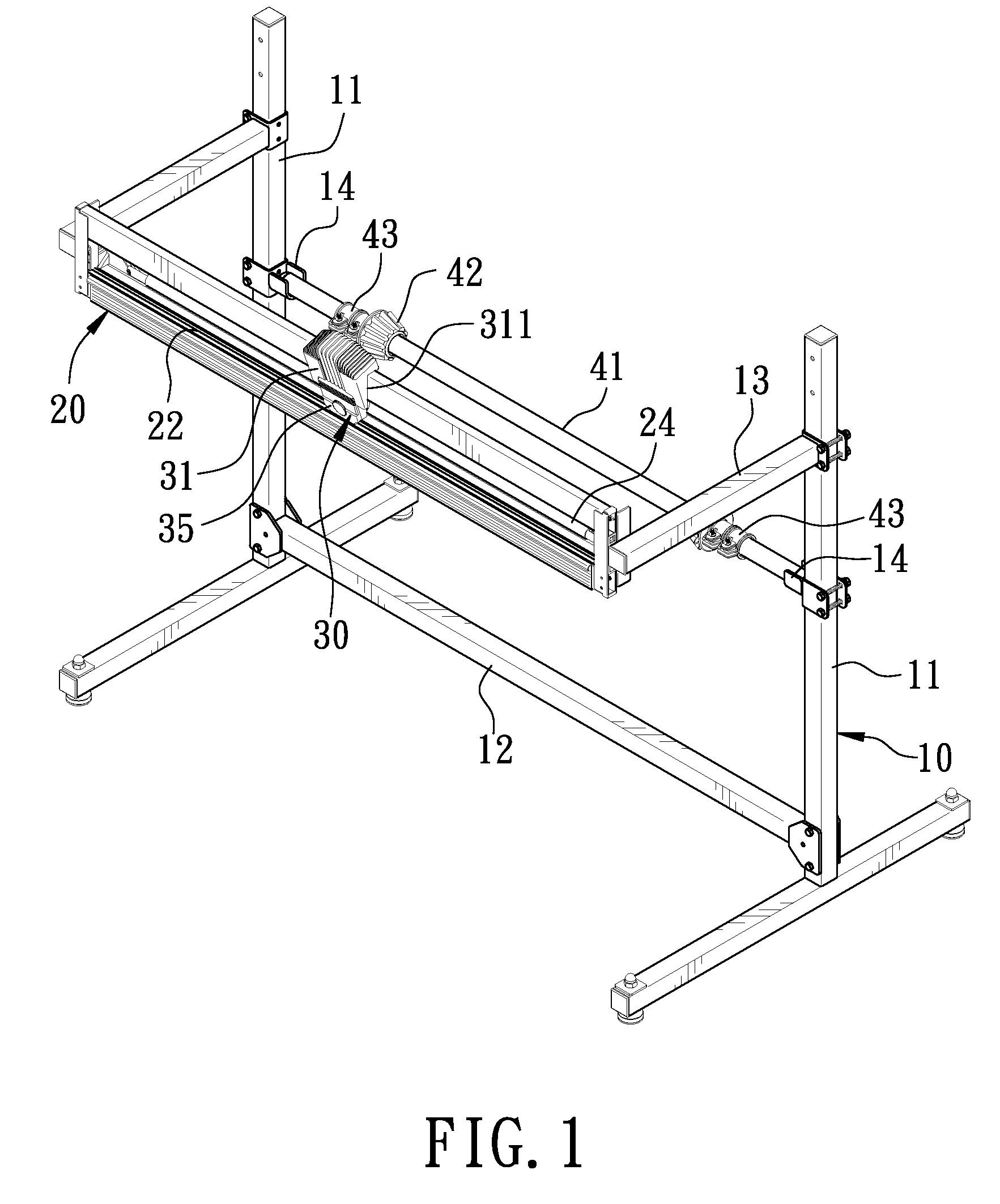
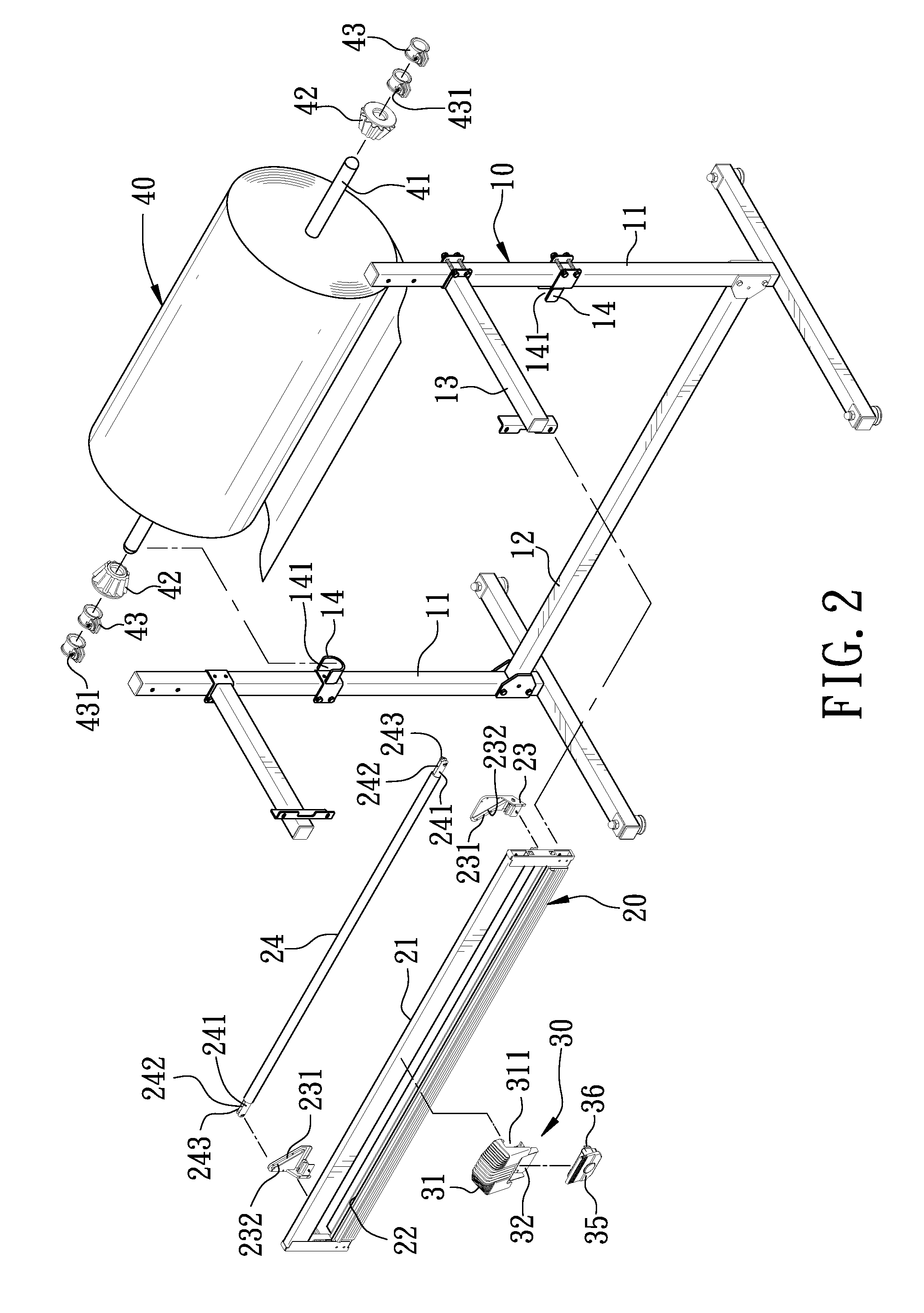
[0015]As shown in FIGS. 1 and 2, a first preferred embodiment of a cutter for cutting a coiled band in the present invention includes a main body 10, a cutting base 20 and a knife unit 30.

[0016]The main body 10 is vertically placed on the ground, provided with a T-shaped post 11 formed at its two sides respectively, reversely standing on the ground in parallel. A transverse rod 12 has its two ends connected to the bottom center of the T-shapes posts 11 respectively, and a front rod 13 is fixed at a preset position of each of the T-shaped posts 11 near the top, extended forward and parallel with each other. The main body 10 is also provided with a U-shaped supporter 14 that is located at a proper position of each of the T-shaped posts 11 below the front rod 13, having an opening facing upward and corresponding to each other. The U-shaped supporters 14 are employed to support two ends of a shaft 41 of a coiled band 40. The shaft 41 has its two ends pivotally engaged with a conical res...


PUM


Abstract

A cutter for cutting a coiled band includes a main body, and a cutting base installed on the main body, having a rectangular frame and a cutting groove formed in the long bottom side of the frame. Respectively fixed at one side and two ends of the cutting base is a sliding plate that has a sliding rail pivotally connected with two ends of a pressing rod respectively, so as to let the front end of the coiled band pass under the pressing rod to run out of the frame while having the pressing rod lifted up. Then, the pressing rod is released to press on the coiled band so as to let a knife unit pivotally connected with the main body flatly and securely cut the coiled band. The cutter is convenient and safe to use, with a cut band being flat and straight.

Description

BACKGROUND OF THE INVENTION[0001]1. Field of the Invention[0002]This invention relates to a cutter, particularly to one used for cutting a coiled band.[0003]2. Description of the Prior Art[0004]Conventionally, if a coiled band is to be cut, its size desired has to be measured first and then, use a table cutter or knife to cut it. It is always time-consuming and inconvenient, especially for cutting a large size. Moreover, hands are possible to be hurt.SUMMARY OF THE INVENTION[0005]The objective of this invention is to offer a cutter for cutting a coiled band.[0006]The main characteristics of the invention are a main body, a cutting base and a knife unit. The cutting base is installed on the main body, provided with a rectangular frame, a cutting groove formed in the long bottom side of the frame, and a sliding plate fixed at one side and two ends of the cutting base respectively. Each of the sliding plates is provided with a sliding rail having its circumference pivotally connecting ...

Claims


Application Information

Patent Timeline
Patent Type & Authority Applications(United States)
IPC IPC(8): B26D1/22B26D1/18B26D7/01
CPCB26D1/065B26D7/025B26D1/185Y10T83/75Y10T83/7507Y10T83/7693Y10T83/7763Y10T83/8722Y10T83/896
Inventor YU CHEN, HSIU-MAN
Owner YU CHEN HSIU MAN
Learn More