Rotation-controllable rotary grip assembly for luggage handle

a rotary grip and handle technology, applied in the field of luggage handles, can solve the problems of affecting the pulling action, the grip may rub against the skin of the hand palm, and the grip may not be kept in balance, so as to achieve the effect of smooth pulling and less effor

Active Publication Date: 2009-04-02
GRP III INT
View PDF8 Cites 8 Cited by
  • Summary
  • Abstract
  • Description
  • Claims
  • Application Information

AI Technical Summary

Benefits of technology

[0005]The present invention has been accomplished under the circumstances in view. It is the main object of the present invention to provide a rotation-controllable rotary grip assembly, which keeps the grip in balance when the grip is rotated relative to the handle of the luggage, so that the user can pull the handle smoothly with less effort.

Problems solved by technology

However, the grip may rub against the skin of the palm of the hand heavily when the hand is kept in a loosened status.
When pulling the handle during walking, the grip may be not kept in balance, affecting the pulling action.

Method used


Image

  • Rotation-controllable rotary grip assembly for luggage handle
  • Rotation-controllable rotary grip assembly for luggage handle
  • Rotation-controllable rotary grip assembly for luggage handle

Examples


Embodiment Construction

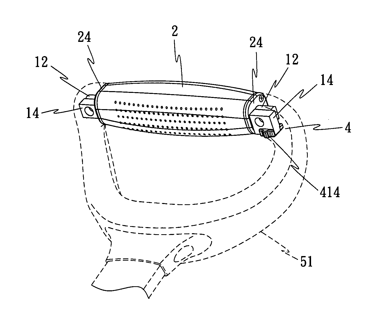
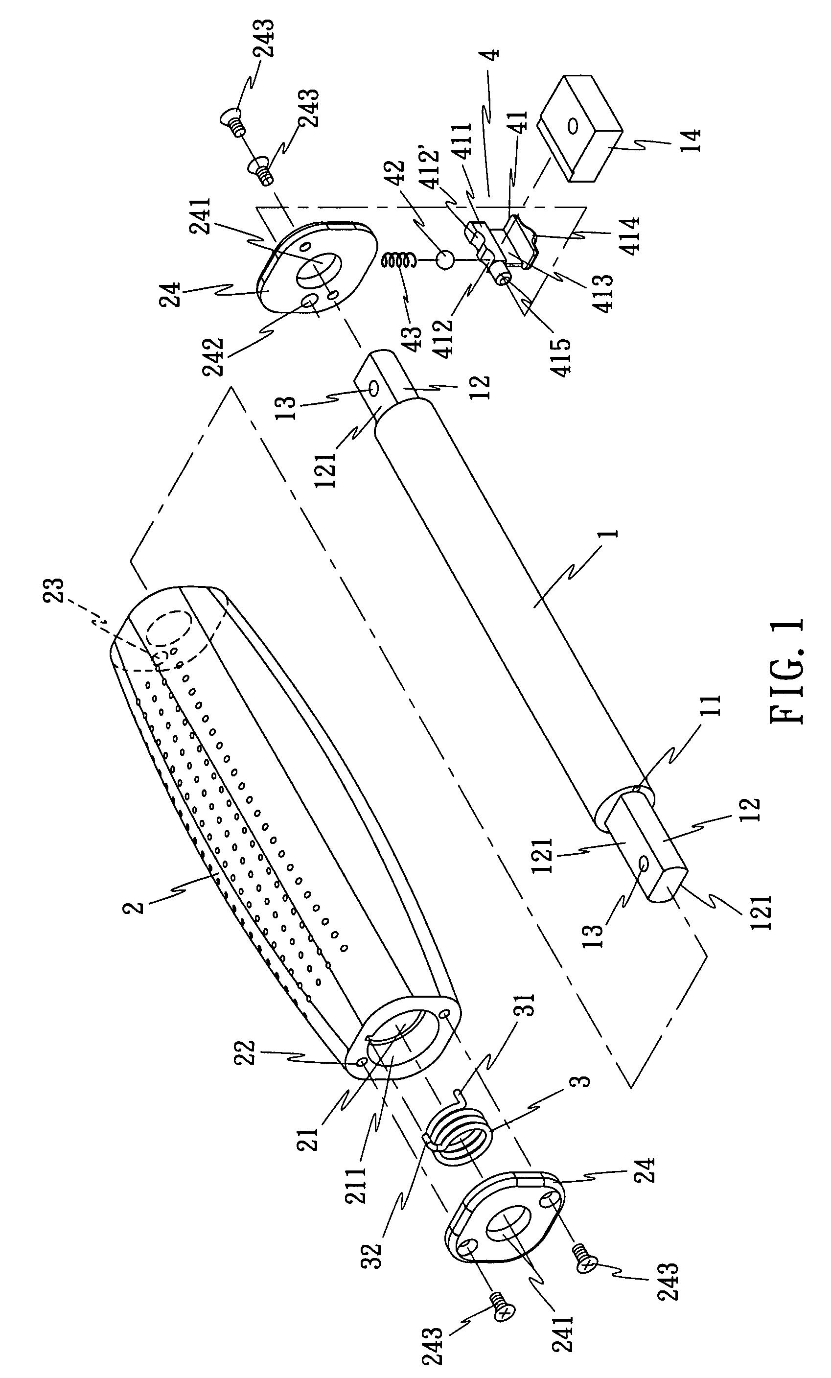
[0017]Referring to FIG. 1, a rotation-controllable rotary grip assembly in accordance with the present invention is shown comprised of a shaft 1, a grip 2, a spring member 3, and a lock 4.

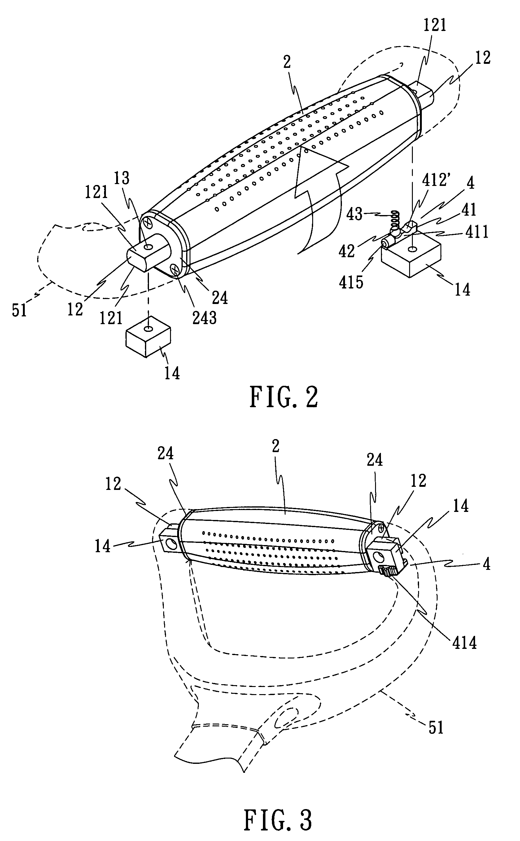
[0018]Referring to FIGS. 2 and 3 and FIG. 1 again, the shaft 1 comprises a locating means, for example, a locating hole 11 on its one end, and two extension rods 12 respectively and axially extending from its two opposite ends. The extension rods 12 each have at least one, for example two planes 121, and a mounting hole 13 cut through the planes 121. Further, a locating block 14 is respectively attached to one plane 121 of each of the extension rods 12. By means of the mounting holes 13 of the extension rods 12 and the locating blocks 14, the shaft 1 is fastened to a handle 51 of a luggage 5 (see also FIG. 10).

[0019]Referring to FIG. 1 again, the grip 2 is shaped like a barrel, having an axial hole 21 axially extending through its two distal ends and coupled to the shaft 1 for allowing turning of t...


PUM


Abstract

A rotation-controllable rotary grip assembly includes a shaft affixed to a retractable handle of a luggage, a barrel-like grip sleeved onto and turntable about the shaft, a spring member sleeved onto one extension rod at one end of the shaft and connected between the shaft and the grip for returning the grip to its former position after a rotary motion of the grip relative to the shaft, and a lock for locking the grip to the shaft to prohibit rotation of the grip relative to the shaft.

Description

BACKGROUND OF THE INVENTION[0001](a) Field of the Invention[0002]The present invention relates to a luggage handle and more specifically, to a rotation-controllable rotary grip assembly for use in a retractable handle of a luggage.[0003](b) Description of the Prior Art[0004]A regular luggage (travel bag), more particularly, a wheeled luggage (travel bag) has a retractable handle for carrying by hand. The retractable handle of a luggage (travel bag) has a grip for the grasping of the hand. When the luggage (travel bag) is standing still on the floor, the retractable handle is kept in vertical. Before moving the luggage (travel bag) on the floor, the user must extend out retractable handle and hold the retractable handle and the luggage (travel bag) in a tilted position. When adjusting the luggage (travel bag) between the vertical position and the tilted position, the user must keep the hand grasping the grip of the retractable handle in a loosened status, preventing heavy friction be...

Claims


Application Information

Patent Timeline
Patent Type & Authority Applications(United States)
IPC IPC(8): A45C13/26A45C13/28
CPCA45C13/262Y10T16/476Y10T16/451
Inventor TONG, JOY
Owner GRP III INT
Why Eureka
Try Eureka