Drive Assist System

Active Publication Date: 2009-04-02
HITACHI ASTEMO LTD
View PDF4 Cites 175 Cited by
  • Summary
  • Abstract
  • Description
  • Claims
  • Application Information

AI Technical Summary

Benefits of technology

[0007]According to the present invention, there can be provided a drive assist system which makes contr

Problems solved by technology

Lane change is a driving action that

Method used


Image

  • Drive Assist System
  • Drive Assist System
  • Drive Assist System

Examples


Embodiment Construction

[0023]A drive assist system according to an embodiment of the present invention is now described with reference to the accompanying drawings.

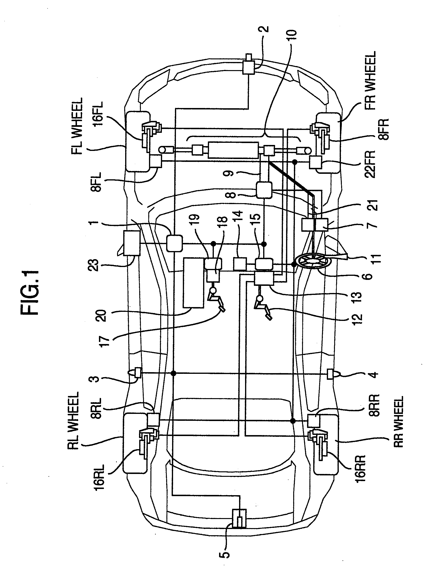
[0024]FIG. 1 is a schematic diagram illustrating the drive assist system. An FL wheel represents a front left wheel, an FR wheel a front right wheel, an RL wheel a rear left wheel and an RR wheel a rear right wheel.

[0025]The drive assist system includes sensors 2, 3, 4 and 5 for recognizing or perceiving the outside of a vehicle, a steering control mechanism 10, a brake control mechanism 13 and a throttle control mechanism 20 for assisting to change a lane on the basis of information recognized by the sensors, a warning device 23, a drive assist controller 1 for calculating command values supplied to the actuators 10, 13 and 20, a steering controller 8 for controlling the steering control mechanism 10 on the basis of the command value from the drive assist controller 1, a brake controller 15 for controlling the brake control mechanism 13 on the...


PUM


Abstract

A drive assist system includes an assist starting part starting assist, a detection part detecting relative distances and speeds between a vehicles, a calculation part calculating collision risks when changing a lane by the basis of the relative distances and speeds, a first judgment part judging whether the lane can be changed by the relative distances, speeds and the collision risks, a decision part deciding a target space for lane change by the relative distances and speeds when the lane cannot be changed, a second judgment part judging whether a lane changeable space is in the target space, a setting part setting a target speed for the vehicle go to a lane change waiting position when no space and to setting a target speed the vehicle enters a lane changeable position when there is the space, and a control part controlling a speed of the vehicle reaches the target speed.

Description

BACKGROUND OF THE INVENTION[0001]The present invention relates to a drive assist system of a vehicle.[0002]Lane change is a driving action that burdens a driver with a heavy load. There is the technique that the space between vehicles is detected to calculate the speed required to change a lane within a certain prediction time in relation to the detected space and control the vehicle on the basis of the speed (refer to JP-A-2005-324727).SUMMARY OF THE INVENTION[0003]In JP-A-2005-324727, the speed suited to make the vehicle change the lane in relation to the space is calculated and accordingly in the circumstances that the surroundings are crowded with vehicles so as not to be able to keep the space between the vehicles, that is, in the circumstances that there is not a safely lane changeable space in a target space, the vehicle cannot be guided so as to change the lane.[0004]Accordingly, it is an object of the present invention to provide a drive assist system which makes control to...

Claims


Application Information

Patent Timeline
IPC IPC(8): G08G1/16B60Q1/00B60R1/00B60R21/00B60W10/00B60W10/04B60W10/06B60W10/18B60W10/184B60W10/20B60W30/00B60W30/09B62D6/00
CPCB60W30/12B60T2201/022
Inventor SUGAWARA, TOSHIHARUYOKOYAMA, ATSUSHINISHIGAITO, TAKAOMIHOSHINO, MASATOSHIYOSHIDA, TATSUYAKUBO, JUNSAITO, SHINJIRO
Owner HITACHI ASTEMO LTD
Why Eureka
Try Eureka