Non-top supported fence installation bracket

a technology of installation brackets and fences, which is applied in the direction of foundation engineering, building roofs, building repairs, etc., can solve the problems of limiting the ability of brackets to support wood fences, affecting the reliability of brackets, and affecting the stability of fences

Inactive Publication Date: 2009-04-16
SANDERS STEVEN H +2
View PDF36 Cites 13 Cited by
  • Summary
  • Abstract
  • Description
  • Claims
  • Application Information

AI Technical Summary

Problems solved by technology

Problems exist with such brackets that can limit the ability of bracket to support a wood fence when exposed to external forces such as wind.
In each of these options, the strength of the structure is compromised such that the bracket cannot be certified to be reliable when subject to forces such as wind.
Further, the issues raised by interference between the reinforcing bar and the bracket can be lengthy and expensive, where excessive man-hours are required to resolve the interference issues when eliminating the bar is not an option.

Method used


Image

  • Non-top supported fence installation bracket
  • Non-top supported fence installation bracket
  • Non-top supported fence installation bracket

Examples


Embodiment Construction

[0021]Although the following detailed description contains many specifics for the purposes of illustration, anyone of ordinary skill in the art will readily appreciate that many variations and alterations to the following exemplary details are within the scope of the invention. Accordingly, the following preferred embodiment of the invention is set forth without any loss of generality to, and without imposing limitations upon, the claimed invention.

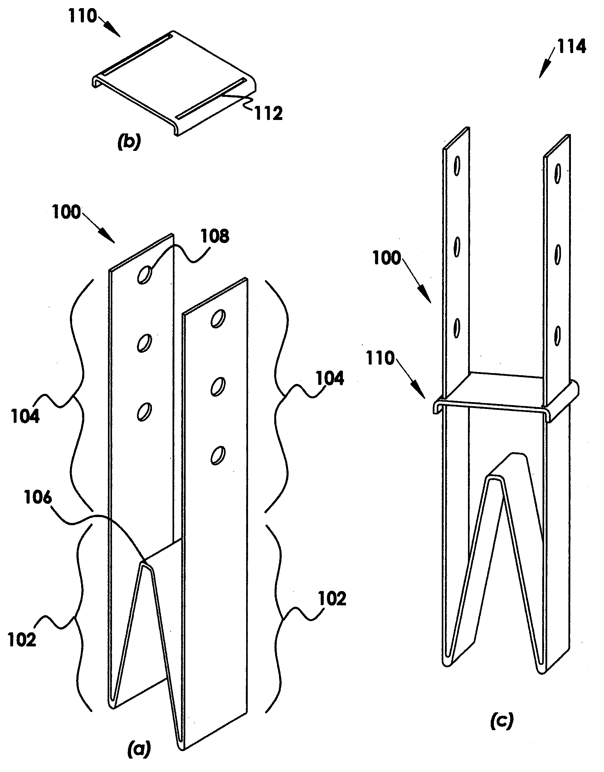
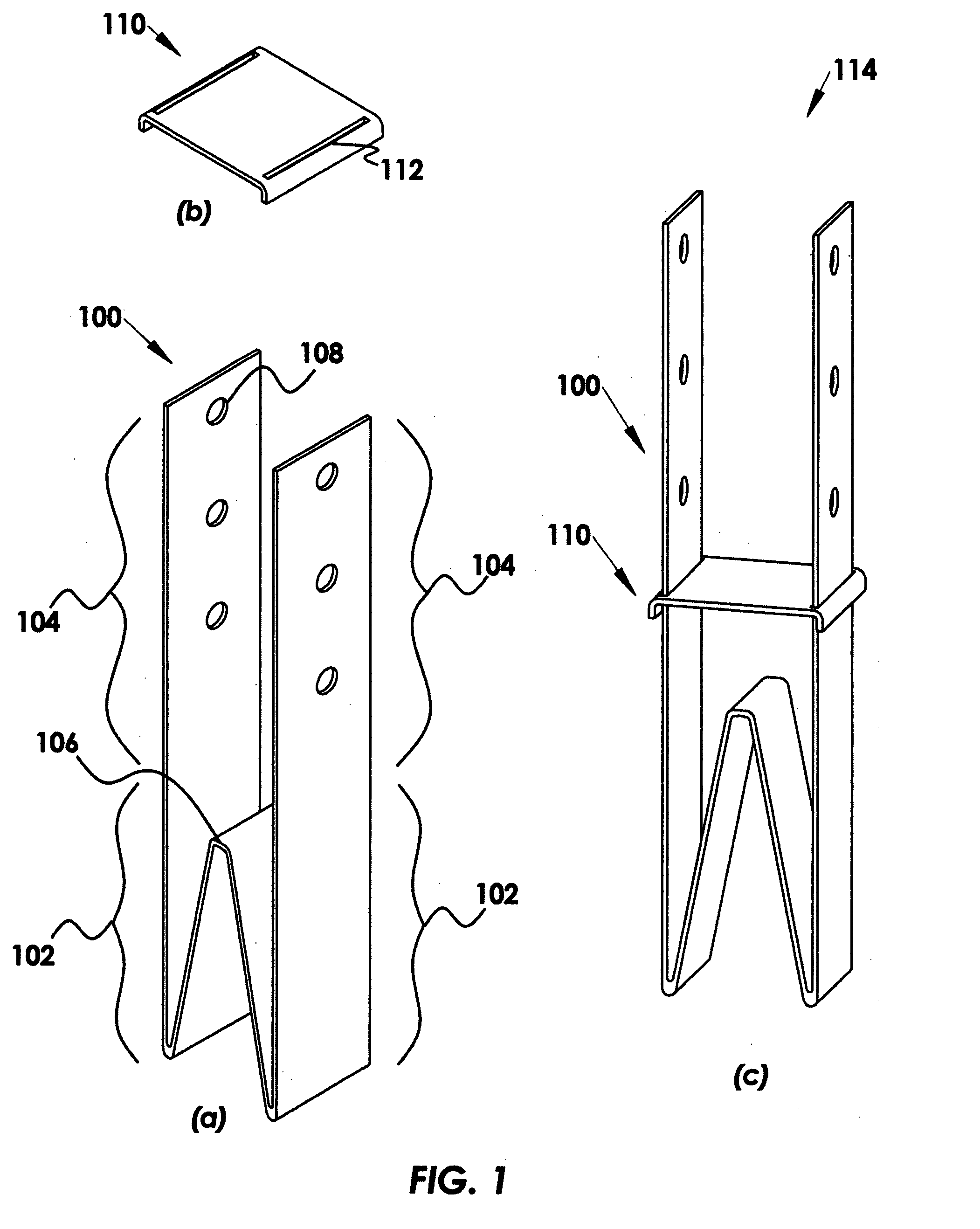
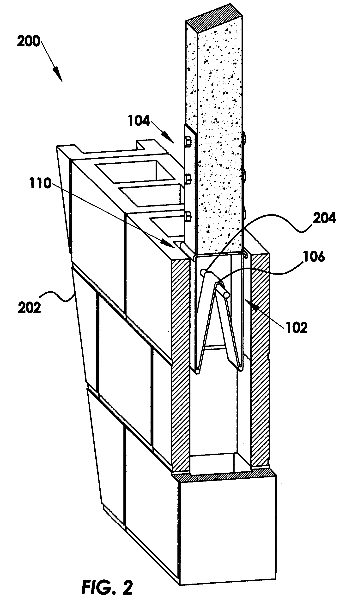
[0022]The current invention includes a generally W-shaped bracket that provides a strong connection between non-top supported wood fences and masonry walls such as concrete masonry unit (CMU) walls or cast in place (CIP) walls. The W-shape provides a matrix inside the hardening structure of the wall, while simultaneously engaging the horizontal reinforcing bar of the wall. The reinforcing bar can be a continuous length of rebar placed in the upper portion of the wall along the wall centerline to provide enhanced wall-strength by distribut...


PUM


Abstract

A non-top-supported column attachment bracket assembly is provided, that includes a generally W-shaped bracket to provide a strong connection between non-top supported wood fences and masonry walls such as concrete masonry unit (CMU) walls or cast in place (CIP) walls. The W-shape provides a matrix inside the hardening structure of the wall, while simultaneously engaging the horizontal reinforcing bar of the wall. The W-anchor further includes a cover plate disposed onto the bracket. The W-shaped bracket can be installed to the upper portion of the wall just prior to grouting or during grouting, where the bracket can be pressed onto the horizontal bar before the grout has hardened. After the hardening structure is cured, fencing posts are attached to a column connection portion of the W-anchor that extends from the top of the wall.

Description

FIELD OF THE INVENTION[0001]The invention relates generally to fence support elements. More particularly, the invention relates to an attachment bracket for connecting fences to cinderblock and / or concrete walls.BACKGROUND[0002]Wall contractors often encounter construction designs having fences attached to masonry walls such as concrete masonry unit (CMU) walls or cast in place (CIP) walls. In such walls, there is typically a horizontal reinforcing bar along the top inner portion of the masonry wall to provide added strength to the structure. A connective interface is required to attach fence posts to the top portion of the masonry wall, where the fence is then connected to the posts. Currently, angle irons, or U-shaped brackets are used to attach the posts of the fence. For example, when using U-shaped brackets to attach wooden fence posts, the bracket base is immersed in unhardened grout poured in the wall top portion, and the fence post is connected to bracket flanges positioned ...

Claims


Application Information

Patent Timeline
Patent Type & Authority Applications(United States)
IPC IPC(8): E04B1/41
CPCE04B1/41E04B2001/268
Inventor SANDERS, STEVEN H.SELL, THOMAS R.COWAN, ANDREW J.
Owner SANDERS STEVEN H
Why Eureka
Try Eureka